York ZJ R-410A User Manual
Page 95
251934-YTG-G-0708
Johnson Controls Unitary Products
95
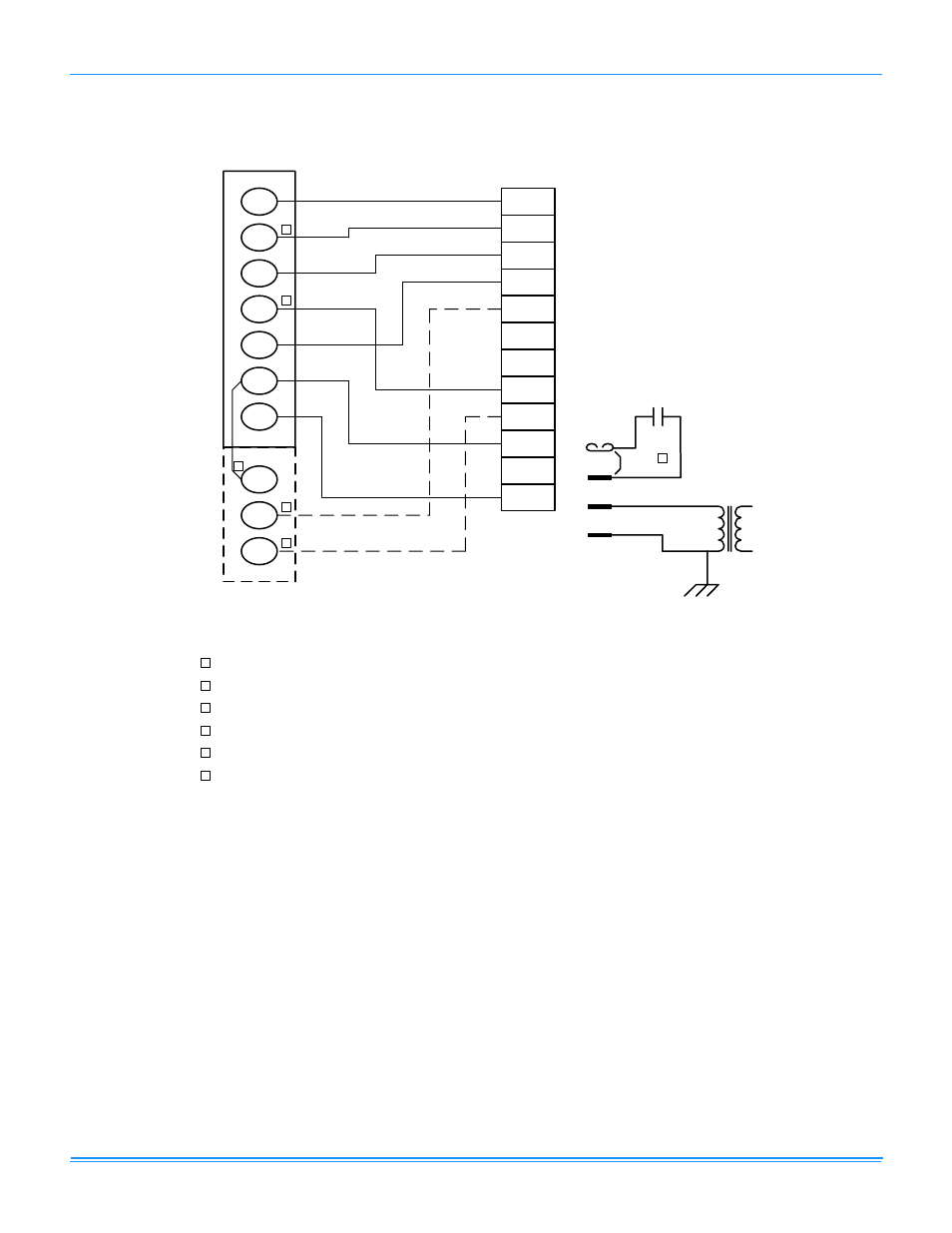
ZF180-300 Typical Control Diagram
W1
W2
Y1
G
OCC
P
P1
Y2
X
R
SD
C
C
SD
SD
R
OCC
C
RC
G
Y2
Y1
W2
W1
Jumper
Smoke
Detector
24 VAC
Class 2
X
R
THERMOSTAT
TERMINALS
CONTROL
TERMINAL
BLOCK
TERMINALS ON
A LIMITED
NUMBER OF
THERMOSTATS
3
1
2
4
3
1
2
4
Second stage heating not required on single stage heating units.
Second stage cooling not required on single stage cooling units.
Jumper is required if there is no Smoke Detector circuit.
Jumper is required for any combination of R, RC, or RH.
6
5
5
6
OCC is an output from the thermostat to indicate the Occupied condition.
X is an input to the thermostat to display Error Status conditions.
See also other documents in the category York Conditioners:
- STELLAR PLUS H4DH018 THRU 060 (20 pages)
- YHJF18 (26 pages)
- YZB018 THRU 060 (40 pages)
- YCW SERIES LD11556 (12 pages)
- YHBC (16 pages)
- DY 036 (36 pages)
- DM 036 (40 pages)
- GHA (12 pages)
- TCGD12 THRU 60 (18 pages)
- FAN COIL YVF/YVS (12 pages)
- CZH024 THRU 060 (16 pages)
- DH 036 (36 pages)
- PREDATOR DJ 150 (28 pages)
- DY 060 (36 pages)
- 12 SEER H*RC036S (24 pages)
- Y32 (96 pages)
- R-22 (4 pages)
- H*BE-F018 (16 pages)
- PREDATOR DM 150 (48 pages)
- PREDATOR 102 (48 pages)
- GY9 (8 pages)
- DNP024 (36 pages)
- SUNLINE DHG 240 (2 pages)
- SUNLINE PLUS D2EG 060 (20 pages)
- PREDATOR DM120 (36 pages)
- LY8S (8 pages)
- SUNLINE MAGNUM DJ 210 (56 pages)
- AHP18 (12 pages)
- DJ 210 (40 pages)
- PREDATOR DR150 (72 pages)
- 13 (4 pages)
- SUNLINE 2000 D1EE 060 (16 pages)
- SUNLINE MAGNADRY WR300 (56 pages)
- YUHC 07-18 (23 pages)
- ECO R-22 (76 pages)
- DJ 180 (40 pages)
- SINGLE PACKAGE AIR CONDITIONING CU060 (28 pages)
- 035-08460-001 (4 pages)
- EVAPORATOR BLOWERS K3EU180 (28 pages)
- THGD18 THRU 60 (30 pages)
- YR (40 pages)
- DM120 (60 pages)
- 10 SEER 50HZ R22 (8 pages)
- CHAMPION PLUS DNP048 (32 pages)
- YCJD18 THRU 60 (18 pages)