Field control wiring, Fig. 5 – field control wiring, Sensor – York ECO R-407C User Manual
Page 34: Space sensor 7 wire thermostat
YORK INTERNATIONAL
34
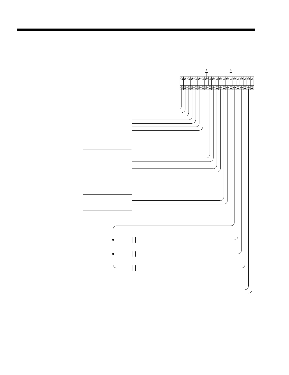
Field Control Wiring
* Use Shielded Wire
* Use Shielded Wire
* Use Shielded Wire
3. Maximum power available from the 24 VAC
1. Wiring shown indicates typical wiring.
Closed = Smoke Purge
Closed = Shutdown
Open = Unoccupied
Closed = Occupied
1.5K Adjust
Signal
cause equipment damage.
power source external of the unit may
sourced from the unit. Use of another
Note, 24VAC switch voltage must be
Relay Output
VAV Heat
Smoke Purge Input
Shutdown Input
Unoccupied Input
Occupied /
to open full.
command the VAV boxes
output shall be used to
Note: VAV Heat Relay
Common
24 VAC Signal
Open = Normal
Potentiometer
Common
0-5V Output
Sensor
Common
Signal
CO
Open = Normal
4. Use shielded wire where shown.
terminal is 40 VA.
2. All wiring is Class 2, low voltage.
Wiring Notes:
Common
Signal
Space Sensor
7 Wire Thermostat
G (Fan)
Y2 (Cool Stage 2)
Y1 (Cool Stage 1)
R (24VAC)
COMMON
RTD Sensor
1K Nickel
IAQ-
IAQ+
COM
SSA-
SSA+
SS-
SS+
R (24 VAC)
3
1
2
4 5
SHIELD
8
6 7
9 10
SHIELD
13
11 12
14 15
Y1
Y2
G
COM
HR
SMK
R (24 VAC)
SD
OCC
18
16 17
19 20 21
2
FIG. 5 – FIELD CONTROL WIRING
LD06158