Charging the unit, Troubleshooting – York DJ150 User Manual
Page 43
035-19046-002-B-0104
Unitary Products Group
43
CHARGING THE UNIT
The DJ150 (12-1/2 Ton) High Efficiency Unit, uses a TXV
metering device. Charge unit to 10º sub-cooling at the TXV.
TROUBLESHOOTING
PREDATOR
MAGNUM FLASH CODES
Various flash codes are utilized by the unit control board
(UCB) to aid troubleshooting. Flash codes are distinguished
by the short on and off cycle used (approximately 200ms on
and 200ms off). To show normal operation, the control board
flashes a 1 second on, 1 second off “heartbeat” during normal
operation. This is to verify that the UCB is functioning cor-
rectly. Do not confuse this with an error flash code. To prevent
confusion, a 1-flash, flash code is not used.
Current alarms are flashed on the UCB LED. The alarm his-
tory can be checked by pressing and releasing the ALARMS
button on the UCB. The UCB will cycle through the last five
(5) alarms, most recent to oldest, separating each alarm flash
code by approximately 2 seconds.
In some cases, it may be necessary to “zero” the ASCD for
the compressors in order to perform troubleshooting. To reset
all ASCDs for one cycle, press and release the UCB TEST
button once.
Troubleshooting of components may require open-
ing the electrical control box with the power con-
nected to the unit. Use extreme care when
working with live circuits! Check the unit name-
plate for the correct line voltage and set the voltme-
ter to the correct range before making any
connections with line terminals.
When not necessary, shut off all electric power to the
unit prior to any of the following maintenance proce-
dures so as to prevent personal injury.
Label all wires prior to disconnection when servicing
controls. Wiring errors can cause improper and dan-
gerous operation which could cause injury to person
and/or damage unit components. Verify proper oper-
ation after servicing.
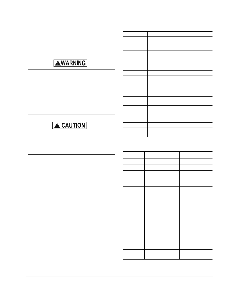
TABLE 28: UNIT CONTROL BOARD FLASH CODES
Flash Code
Description
On Steady
Control Failure - Replace Control
Heart Beat
Normal Operation
1 Flash
Not Applicable
2 Flashes
Control waiting ASCD
*
*.
These flash codes do not represent alarms.
3 Flashes
HPS1 - Compressor Lock out
4 Flashes
HPS2 - Compressor Lock out
5 Flashes
LPS1 - Compressor Lock out
6 Flashes
LPS2 - Compressor Lock out
7 Flashes
FS1 - Compressor Lock out
8 Flashes
FS2 - Compressor Lock out
9 Flashes
Ignition Control Locked Out/
Ignition Control Failure / Limit Switch Trip / No
Jumper Plug in Heat Section
10 Flashes
Compressors Locked Out On Low
Outdoor Air Temperature
*
11 Flashes
Compressors Locked Out Because The
Economizer Is Using Free Cooling
*
12 Flashes
Fan Overload Switch Trip - Not Applicable On This
Unit
13 Flashes
Compressor Held Off Due To Low Voltage*
14 Flashes
EEPROM Storage Failure (Control Failure)
OFF
No Power or Control Failure
TABLE 29: IGNITION CONTROL FLASH CODES
FLASHES
FAULT CONDITIONS
CHECK
STEADY ON
Control Failure
Control
HEARTBEAT
Normal Operation
1
Not Applicable
2
Pressure Switch
Stuck Closed
Pressure Switch
3
Pressure Switch Failed
To Close
Venter Pressure Switch
Vent Blocked
4
Limit Switch Open
Main Limit
AUX Limit
5
Flame Present With Gas
Off First Stage Gas Valve
Energized With W1 Off
Second Stage Gas Valve
Energized With First
Stage
Gas Valve Off
Gas Valve
6
Ignition Lockout
Gas Flow
Gas Pressure
Gas Valve
Flame Sensor
STEADY OFF
No Power Or Control
Failure
24VAC or Control