Figure 7 - unit dimensions, Table 6: unit clearances, Detail a – York DJ150 User Manual
Page 13: Detail b, Detail c
035-19046-002-B-0104
Unitary Products Group
13
NOTE:
A one-inch clearance must be provided between
any combustible material and the supply ductwork
for a distance of 3 feet from the unit.
NOTE:
If the unit includes gas heating, locate the unit so
the flue exhaust is at least:
•
Three (3) feet above any forced air inlet located within 10
horizontal feet (excluding those integral to the unit).
•
Four (4) feet below, four (4) horizontal feet from, or one
(1) foot above any door or gravity air inlet into the build-
ing.
•
Four (4) feet from electric meters, gas meters, regula-
tors, and relief equipment.
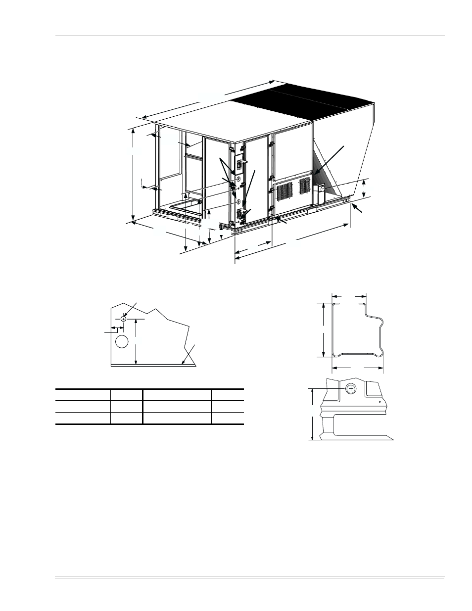
FIGURE 7 -
UNIT DIMENSIONS
50-3/4
4-1/4
59
30-3/16
24-3/16
17-3/16
27
89
11-1/2
LEFT
FRONT
For Drain Dimensions
See Detail C
See Detail A
119-7/16
Power
Entry
2-1/2
Con-
venience
Outlet
For
Baserail
Dimensions
See
Detail B
6-3/16
30-11/32
Control
Entry 7/8
Con-
venience
Outlet
Power
Entry
7/8
TABLE 6:
UNIT CLEARANCES
Top
*
*.
Units must be installed outdoors. Overhanging struc-
ture or shrubs should not obstruct condenser air dis-
charge outlet.
72”
Right
12”
Front
†
†.
The products of combustion must not be allowed to
accumulate within a confined space and re-circulate.
36”
Left
36”
Rear
‡
‡.
To remove the slide-out drain pan, a rear clearance of
sixty inches is required. If space is unavailable, the
drain pan can be removed through the front by separat-
ing the corner wall.
36”
Bottom
**
**.
Units may be installed on combustible floors made from
wood or class A, B or C roof covering materials.
0”
5 - 1 / 4
B a s e
P a n
1 7 - 1 3 / 1 6
V i e w o f W a l l A c r o s s f r o m C o i l
G a s P i p e I n l e t
DETAIL A
3 - 3 / 4
3 - 9 / 1 6
2 - 3 / 8
DETAIL B
5 - 3 / 8
DETAIL C