Table 21, Fig. 3 - clearances – York B1HH018 User Manual
Page 13
Unitary Products Group
13
66297-YIM-C-0205
TABLE 21 -
ADDITIONAL STATIC PRESSURE RESISTANCE
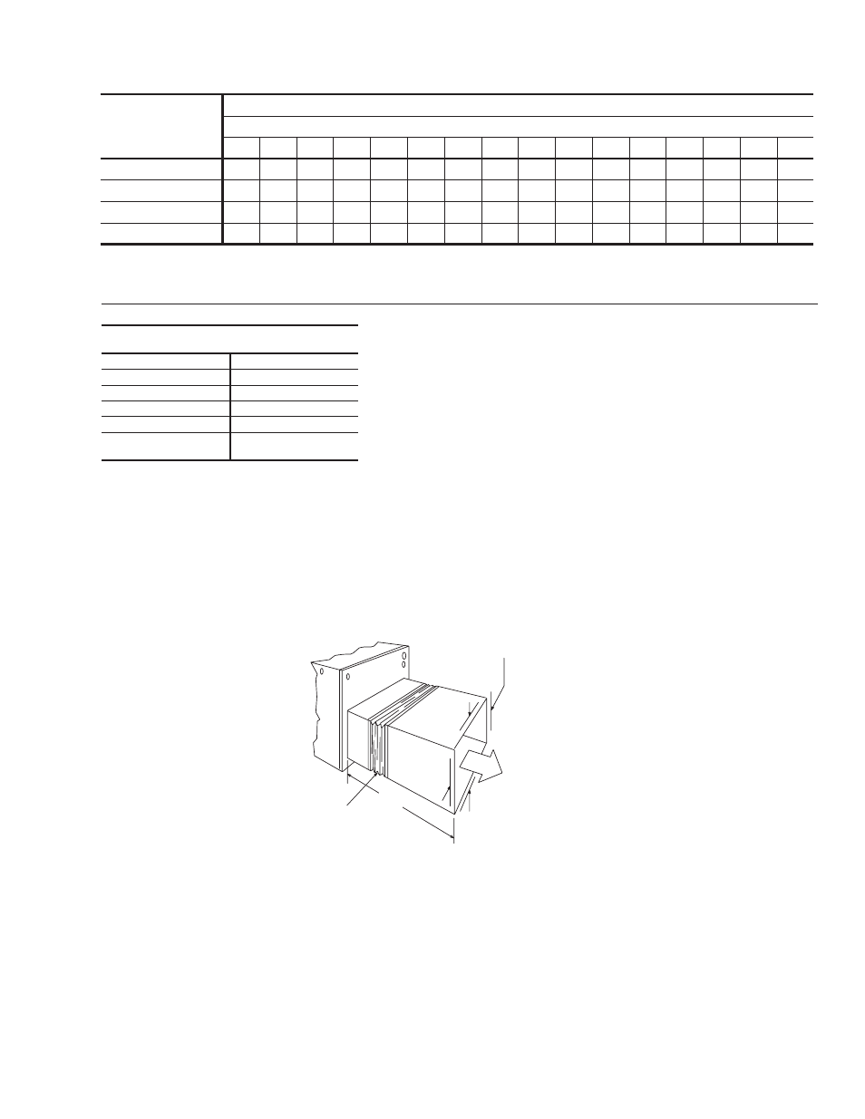
FIG. 3 - CLEARANCES
DESCRIPTION
RESISTANCE, IWG
CFM
500
600
700
800
900
1,000 1,100 1,200 1,300 1,400 1,500 1,600 1,700 1,800 1,900 2,000
Wet Indoor coil
0.01
0.01
0.01
0.02
0.01
0.02
0.03
0.04
0.04
0.03
0.04
0.04
0.05
0.05
0.06
0.07
Economizer
0.00
0.00
0.00
0.01
0.01
0.01
0.01
0.02
0.03
0.04
0.05
0.06
0.07
0.07
0.08
0.08
Filter/Frame Kit
0.01
0.02
0.02
0.02
0.02
0.02
0.03
0.03
0.03
0.03
0.04
0.05
0.05
0.06
0.06
0.07
Electric Heat
0.02
0.03
0.03
0.03
0.04
0.04
0.05
0.06
0.07
0.08
0.09
0.10
0.01
0.11
0.11
0.12
NOTE: 1. Deduct these resistance values from the available external static pressure shown in the respective Blower Performance Table.
2. The pressure thru the economizer is greater for 100% outdoor air then for 100% return air. If the resistance of the return air duct system is less then 0.25 IWG, the unit will deliver
less CFM during full economizer operation.
CLEARANCES
(Minimum)
Front
12"
Back
0"
Left Side (Filter Access) 24"
Right Side
24"
Below Unit
Q
0"
Above Unit
R
36" (For Condenser
Air Discharge)
Q
Units may be installed on combustible floors made from wood or class A,
B or C roof covering material.
R
Units must be installed outdoors. Overhanging structures or shrubs
should not obstruct outdoor air discharge outlet.
3'
M IN IM UM C LEARANCE O F 1 "
ALL S ID ES F O R T H E F IR ST 3 '
O F D UCT F O R 2 0 & 2 5 k W .
ZERO IN CHES T HER EAFTER,
FO R A LL O TH ER H EATERS,
ZERO IN CH C LEARANCE A LL
SID ES F O R E N TIRE L EN G TH
O F D UCT.
FLEXIB LE D U CT
CO LLAR
NOTE: FOR UNITS APPLIED WITH A ROOF
CURB, THE MINIMUM CLEARANCE MAY BE
REDUCED FROM 1 INCH TO 1/2 INCH BE-
TWEEN COMBUSTIBLE ROOF CURB MA-
TERIAL AND THE SUPPLY DUCT.