Xantrex Technology Xantrex AC to DC Converter XADC User Manual
Page 19
Installation Instructions
975-0301-01-01
19
3. Connect the incoming negative (-) black cable from each of the loads to the
negative DC bus.
4. Connect the incoming positive (+) red cable from each of the loads to the
positive DC bus.
5. Install fuses for the DC loads and the DC battery. The bottom four DC fuses
are for the battery. Fuses for DC loads should be Littelfuse Type 257 or
equivalent and the maximum allowed fuse for the DC loads is 20 A.
6. Connect the incoming negative (-) black cable from the battery to the negative
DC battery lug.
7. Connect the incoming positive (+) red cable from the battery to the positive
DC battery lug.
8. Tighten the clamp screws on the strain relief to secure the DC wires.
Important:
You may remove the PCB with the positive DC bus and fuse holders (by
removing the three screws) for ease of connection. Keep the screws for reconnecting the
PCB. See Figure 13.
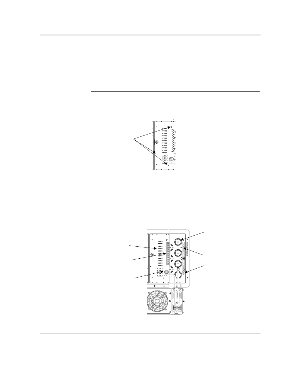
Figure 13 DC PCB Removal
Remove these
three screws
Figure 14 Connecting DC to the Panel
Positive DC bus
DC fuses
DC Knockouts
Negative DC bus
Positive DC
battery lug
Negative DC
battery lug