Counterbalance cables/ bottom brackets, Fig a, Fig b – Wayne-Dalton 451 User Manual
Page 4: Fig c fig d
4
COUNTERBALANCE CABLES/ BOTTOM BRACKETS
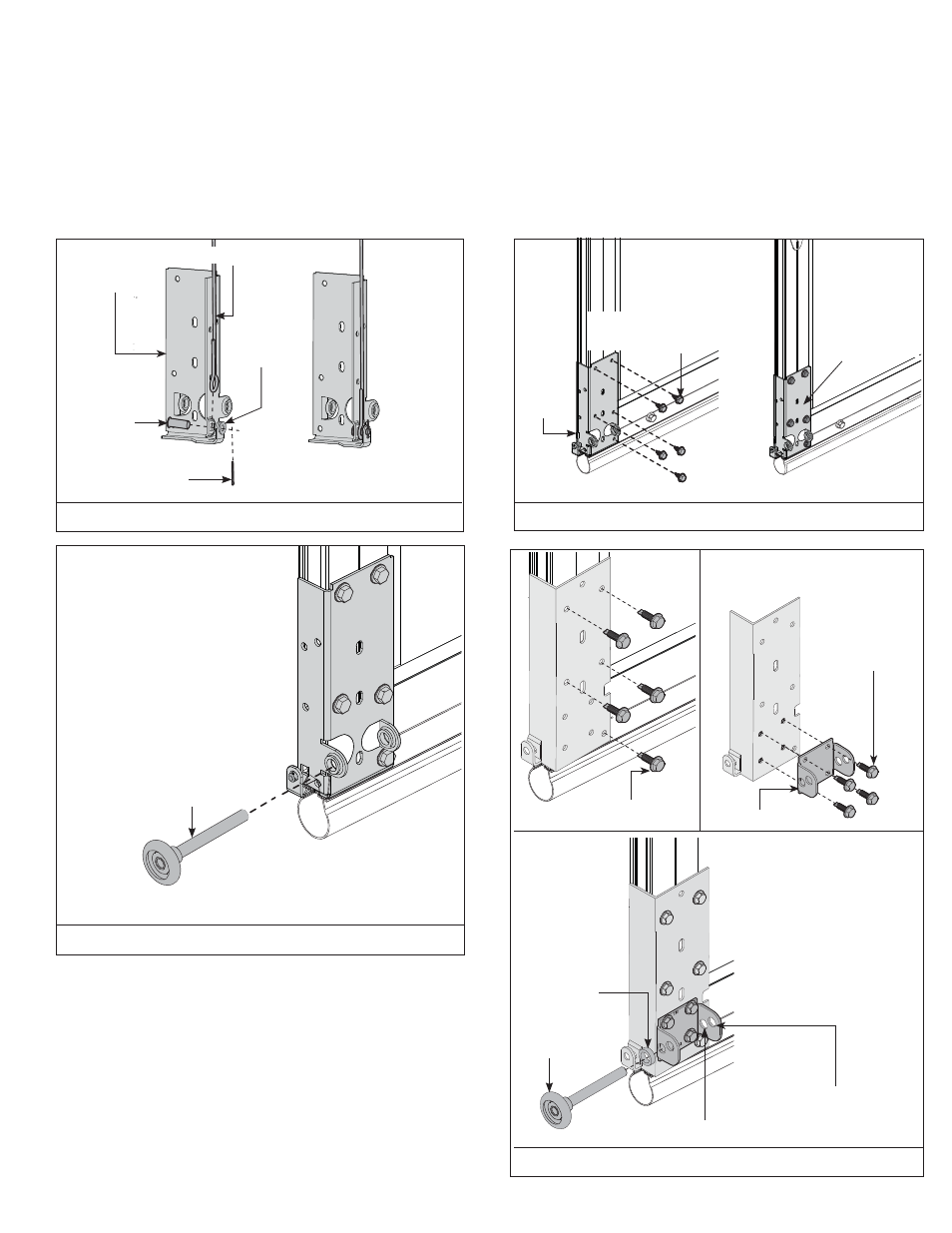
For doors using the broken cable safety device, see page 19.
For Model 451 doors with the bottom bracket shown in FIG A, locate the bottom section and the left and right hand bottom brackets. Secure the counterbalance cables to the brackets using
clevis pin, washer and cotter key as shown in FIG A. Secure bottom brackets to bottom section using (5) 1/4” x 7/8” self-drilling screws as shown in FIG B. Insert a roller into the bottom
brackets as shown in FIG C.
For Model 451 doors with the bottom bracket shown in FIG D, Secure the counterbalance cables in the same manner as described above. Attach the bracket to the section with (5) 1/4” X
7/8” self drilling screws. Attach the roller carrier to the bottom bracket with (4) 1/4” X 7/8” self drilling screws. Insert a roller and 3/16” roller spacer into the roller carrier; the inner holes of
the roller carrier are for 2” track; the outer holes of the roller carrier are for 3” track.
FIG A
COTTER KEY
CLEVIS PIN
FIG B
BOTTOM BRACKET
BOTTOM
BRACKET
ASSEMBLY
(5) 1/4” X 7/8” SELF
DRILLING SCREWS
BOTTOM
SECTION
ATTACHED
BOTTOM BRACKET
ASSEMBLY
BOTTOM
SECTION
COUNTERBALANCE CABLE
ROLLER
FIG C
FIG D
(5) 1/4” X 7/8” SELF
DRILLING SCREWS
WASHER
ROLLER CARRIER
(4) 1/4” X 7/8” SELF
DRILLING SCREWS
ROLLER
3/16”
ROLLER
SPACER
INNER HOLES FOR 2” TRACK
OUTER HOLES FOR 3” TRACK