Warning, Fig q spring turn chart, Winding springs – Wayne-Dalton 451 User Manual
Page 12
12
DOOR HEIGHT
400-8
400-12
5250-18
800-32
6’6”
7.5
7.5
7’0”
7.875
7.875
7’6”
8.5
8.5
8’0”
8.875
8.875
6.75
8’6”
9.25
7.125
9’0”
9.5
7.375
9’6”
10.125
7.75
10’0”
10.5
8.125
5.375
10’6”
11
8.375
5.625
11’0”
11.5
8.875
5.875
11’6”
12
9.125
6
12’0”
12.5
9.5
6.25
12’6”
9.875
6.5
13’0”
10.25
6.75
13’6”
10.5
7
14’0”
10.875
7.375
14’6”
11.25
7.5
15’0”
11.5
7.625
15’6”
11.875
8
16’0”
12.25
8.125
16’6”
12.5
8.25
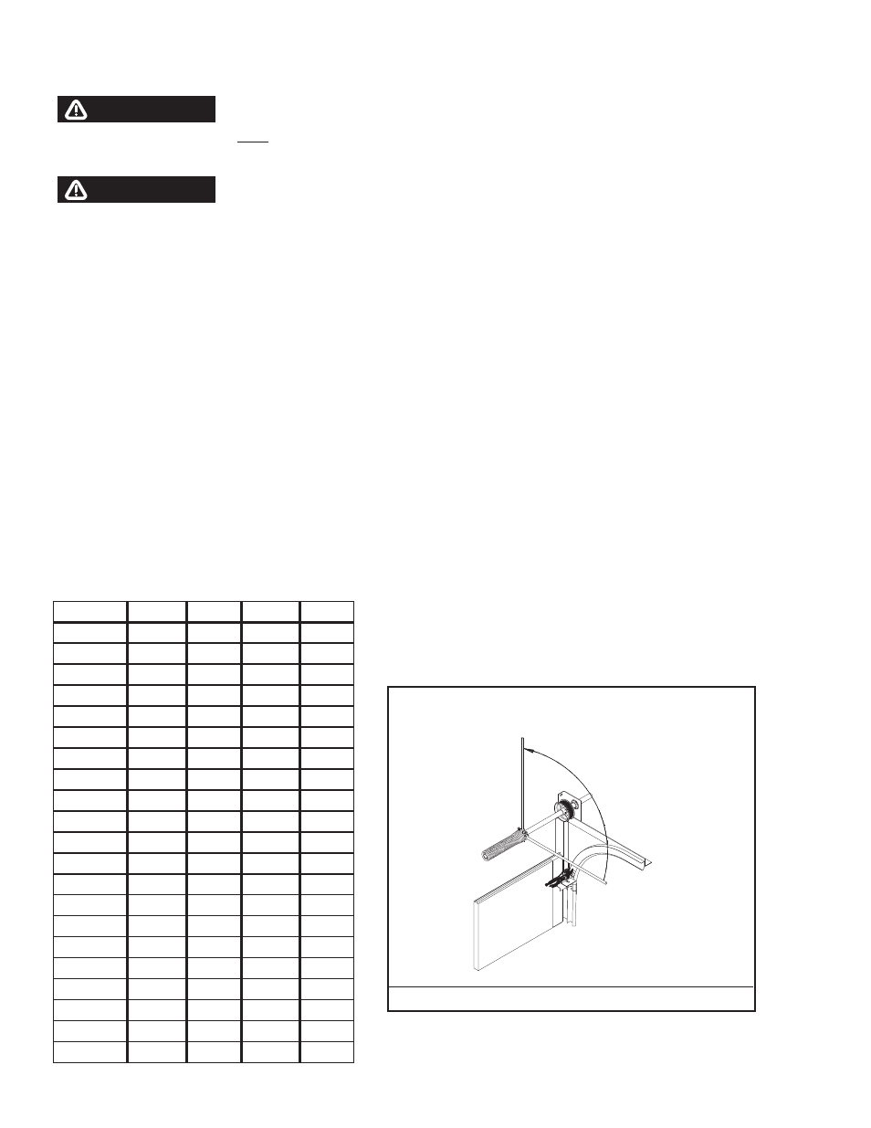
FIG Q
SPRING TURN CHART
WIND SPRINGS
TOWARD CEILING.
(STANDARD LIFT
APPLICATIONS)
WARNING
WARNING
WINDING SPRINGS
APPLY LOCKING PLIERS TO THE TRACKS ABOVE THE THIRD ROLLER, OR LOCK DOOR IF APPLICABLE, BEFORE WINDING THE SPRING(S) TO PREVENT DOOR FROM
RISING UNEXPECTEDLY, POSSIBLY RESULTING IN SEVERE OR FATAL INJU RY.
WINDING BARS MUST FIT SNUGGLY INTO HOLES IN SPRING WINDING CONES. ATTEMPTING TO WIND SPRINGS WITH LOOSELY FITTING RODS, SCREWDRIVERS OR
OTHER IMPROPER TOOLS CAN RESULT IN SEVERE OR FATAL INJURY.
Feed the cable attached to the left hand bottom bracket up the vertical track, behind the rollers and secure to the left hand drum. Push the drum up against the end
bearing bracket and secure to the shaft by tightening the set screws (solid shafts use 1/4” key(s) and set screws to secure drums).
Rotate drum and shaft until cable is taut, then apply locking pliers to torsion shaft with end resting against header. This will hold cable taut and on drum. There must be
at least 1/2 wrap of cable on the drum. If not, contact Wayne-Dalton for proper length cables. Attach other cable to right hand drum. Push drum against end bearing
bracket and rotate drum until cable is taut. Secure drum to shaft by tightening the set screws. Cable tension must be equal on both drums on single shaft applications.
On split shaft applications, apply locking pliers to both torsion shafts, and secure bolts in coupling after springs are fully wound.
Carefully, following spring winding instructions detailed in FIG Q, wind spring(s), using the appropriate 1/2”, 5/8” or 3/4” diameter winding rods of suffi cient length; wind
spring 1/4 turn at a time to the number of complete revolutions recommended on the spring turn chart. When the proper number of turns is reached, tighten the set
screws on the winding cone. Release the locking pliers from the spring shaft(s). Adjust the coupler on split solid shafts until drums are in line (check door level) and
tighten coupler.
NOTE: Coupling used on solid shaft only. Tighten connecting bolts after winding springs.