Fig x step plate installation, Exhaust port installation, Fig w – Wayne-Dalton 451 User Manual
Page 16
16
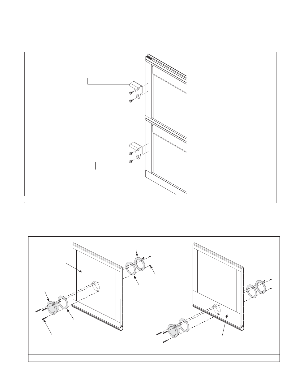
FIG X
STEP PLATE INSTALLATION
Position your step plate, on the inside of the door, over the bottom section end stile on the side of the door containing the side lock. Secure step plate to endstile with
(2) 1/4”-20 x 7/8” Self-drilling screws, as shown in FIG W. For doors ordered with non-keyed locks, a second step plate is provided. Install the second step plate in the
same manner as the fi rst, on the lock section (second section), below the side lock.
END STILE
(2) 1/4”-20 X 7/8” SELF-
DRILLING SCREWS
BOTTOM SECTION
STEP PLATE
LOCK SECTION
IF SECOND STEP PLATE WAS
RECEIVED FOR DOORS ORDERED
WITH NON-KEYED LOCKS, INSTALL
IT BELOW THE SIDE LOCK.
EXHAUST PORT INSTALLATION
Install the exhaust port using (3) #10 x 1-1/2” counter sunk bolts and nuts, as shown in FIG X.
Exhaust port goes on the inside of bottom section and can be installed into the aluminum panel or a double wide bottom rail.
OUTSIDE TRIM RING
(3) #10 X 1-1/2”
COUNTER SUNK BOLT
EXHAUST PORT
GASKET
(3) #10 HEX NUTS
FIG W
GASKET
ALUMINUM PANEL
DOUBLE WIDE
BOTTOM RAIL