Fig z – Wayne-Dalton 451 User Manual
Page 18
18
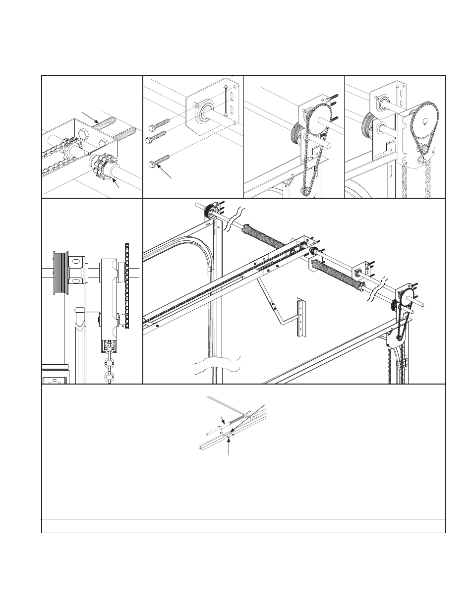
SINGLE TROLLEY OPERATOR BRACKET IS DOOR SIZE DEPENDENT.
TROLLEY OPERATOR BRACKET IS SUPPLIED BY OTHERS
COUPLING
5” MIN. EXTRA HEADROOM REQUIRED
1/2” X 3” MIN. SLEEVE
ANCHOR (BY OTHERS),
5/16” X 1” SELF-DRILLING
AND TAPPING SCREW OR
5/16” X 1-5/8” LAG BOLT
1/2” X 3” MIN. SLEEVE
ANCHOR (BY OTHERS),
5/16” X 1” SELF DRILLING
AND TAPPING SCREW OR
5/16” X 1-5/8” LAG BOLT
NOTE: Install Sprocket or chain
hoist as close to track as possible,
minimum of 3/4”, to minimize shaft
defl ection.
Pusher Spring Installation:
Raise door until bottom section is 3/4” below header. Align pusher spring with the top corner of the top section. (Compress against the top bracket fl ange.)
Drill (2) 3/8” holes in each track and secure using (2) 3/8” x 1-1/4” hex head bolts and nuts. (bolt may extend into track.)
PUSHER SPRING
(2) 3/8” DIAMETER
HOLES
(2) 3/8” X 1-1/4”
HEX HEAD BOLTS
AND NUTS
TOP SECTION
FIG Z