Configuration, Select battery type, Select high ac voltage switch to battery point – Tripp Lite Alternative Power Sources User Manual
Page 5: Select low ac voltage switch to battery point, Dip switch group b (available on select models)
5
Configuration
CONFIGURATION DIP SWITCH SETTINGS
DIP SWITCH GROUP A (All models)
BATTERY TYPE / VOLTAGE POINT
Using a small tool, set the 4 “Battery Type / Voltage Point” Configuration DIP Switches, Group A
(located on the front panel of your APS; see Diagram 1, p. 32) to select battery type and set the
voltage range outside of which your APS will switch to battery power.
• Select Battery Type
(DIP Switch #1, Group A)
CAUTION: The Battery Type DIP Switch setting must match the type of batteries you connect or your batteries may be degrad-
ed or damaged over an extended period of time. See “Battery Selection,” page 7 for more information.
Battery Type
Switch Position
Gel Cell (Sealed) Battery ............................Up
Wet Cell (Vented) Battery ............................Down*
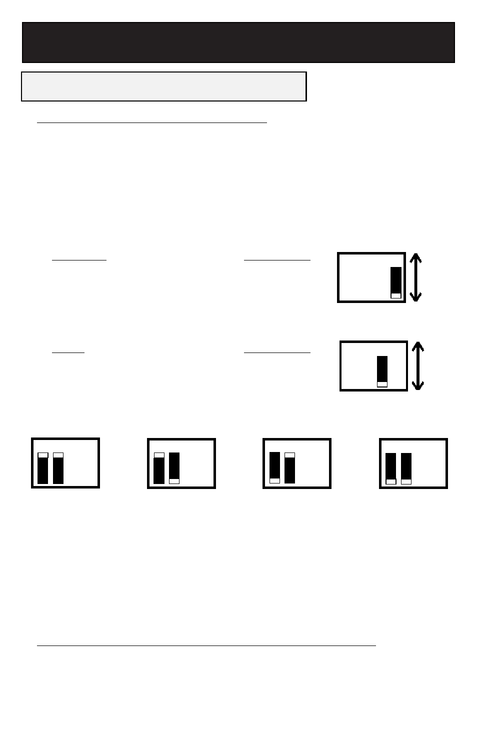
• Select High AC Voltage Switch To Battery Point
(DIP Switch #2, Group A)
Voltage
Switch Position
264V ............................................................Up
259V ............................................................Down*
• Select Low AC Voltage Switch To Battery Point
(DIP Switches #4, Group A & #3, Group A)
Most loads will perform adequately when your APS’s High AC Voltage Point DIP Switch #2 is set
to 259V and its Low AC Voltage Point DIP Switches #3 and #4 are set to 182V. However, if your
APS frequently switches to battery power due to momentary high/low line voltage swings that
would have little effect on equipment operation, you may wish to adjust these settings. By raising
the High AC Voltage Switch to Battery point and/or lowering the Low AC Voltage Switch to Battery
Point, you may reduce the number of times your APS switches to battery due to voltage swings.
* Factory default settings.
DIP SWITCH GROUP B (Available on Select Models)
LOAD SHARING/EQUALIZE BATTERY CHARGE
Using a small tool, set the “Load Sharing” Configuration DIP Switches, #1 and #2 of Group B
(located on the front panel of your APS; see Diagram 1, p. 32). DIP Switch #3, Group B should
be kept in the “UP” position when you are not equalizing your batteries' charges. DIP Switch #4,
Group B has different functions, or no function, depending on your APS model.
144V*
#4 Down
& #3 Down
163V
#4 Down & #3 Up
182V
#4 Up & #3 Down
201V
#4 Up & #3 Up
Gel
Cell
Wet
Cell*
264V
259V*
4
4 3
3 2
2 1
1
4
4 3
3 2
2 1
1
4
4 3
3 2
2 1
1
4
4 3
3 2
2 1
1
4
4 3
3 2
2 1
1
4
4 3
3 2
2 1
1