Data sheet: maxeta, Ifa series, Electrical data – TDK Maxeta iFA Series User Manual
Page 6
Data Sheet: Maxeta
TM
iFA Series
©2002-2006 TDK Innoveta Inc.
iFA 28V 600W Advance Datasheet 8/3/2006
℡
(877) 498-0099
6/19
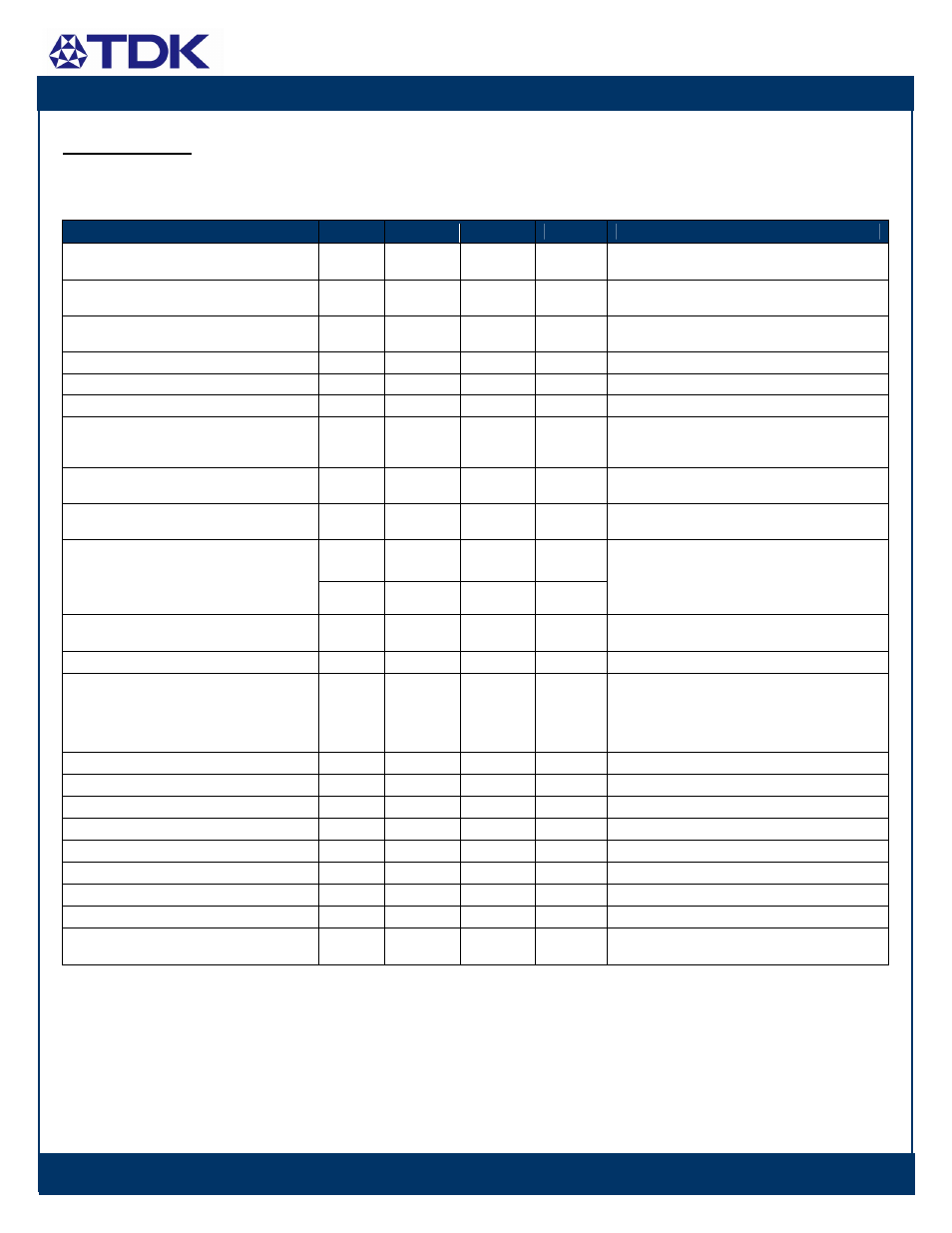
Electrical Data:
iFA48021A280V- 000 through - 003: 28V, 21.4A Output
Characteristic
Min
Typ
Max
Unit
Notes & Conditions
Output Voltage Initial Set-point
27.51
28
28.49
Vdc
Vin=Vin,nom; Io=Io,max; Tc = 25˚C
Output Voltage Tolerance
27.16
28.84
Vdc
Over all rated input voltage, load, and
temperature conditions to end of life
Efficiency
---
90.5
---
%
Vin=Vin,nom; Io=Io,max; Tc = 25˚C
Line Regulation
---
28
56
mV
Vin=Vin,min to Vin,max, Io and Tc fixed
Load Regulation
---
28
56
mV
Io=Io,min to Io,max, Vin and Tc fixed
Temperature Regulation
---
100
300*
mV
Tc=Tc,min to Tc,max, Vin and Io fixed
Output Current
3.75
---
21.4
A
At loads less than Io,min the module will
continue to regulate the output voltage, but the
output ripple may increase
Output Current Limiting Threshold
22*
24
26*
A
Vo = 0.9*Vo,nom, Tc Short Circuit Current --- 0.5 --- A Vo = 0.25V, Tc = 25˚C --- 135 250* mVpp Output Ripple and Noise Voltage --- 20 50* mVrms Vin=48V, Io ≥Io,min, Tc = 25˚C, with a 0.1µF, a 10 µF ceramic, and a 470µF low esr aluminum capacitors located 2 inch away. S ee input & output ripple measurement figure; BW = 20MHz Output Voltage Adjustment Range 60 --- 110 %Vo,nom Po ≤Po,max, refer to “Output Voltage Adjustment” figure for Vin,min requirement Remote Output Voltage Sense Range 0.5* --- --- Vdc Dynamic Response: --- --- 0.5 450 --- --- mS mV di/dt = 0.1A/uS, Vin=Vin,nom; Tc = 25˚C, load Output Voltage Overshoot during Startup 0 0 600* mV Io=Io,max,Tc=25˚C Switching Frequency --- 175 --- kHz Fixed Output Over Voltage Protection 31.9* 34.2 35.5* V External Load Capacitance 450 --- 6,000 ** uF Minimum ESR > 1mΩ Isolation Capacitance --- 1000 --- pF Isolation Resistance 10 --- --- MΩ Load Share Accuracy -10 --- +10 % 50% to 100% rated load current Power Good Pin Max Applied Voltage --- --- 35 Vdc Max sink current 5mA Auxiliary Output Voltage 7.5* 10 13.5* Vdc Max Aux pin current ≤ 20mA Referenced to sense(-) pin.
Settling Time to 10% Peak Deviation
Peak Voltage Deviation
step from 50% to 75% of Io,max.
With at least a 10uF ceramic capacitor and a
470uF low esr aluminum or tantalum capacitor
across the output terminals.
* Engineering Estimate
** Contact Innoveta for applications that require additional capacitance or capacitors with very low esr