Data sheet: maxeta, Ifa series – TDK Maxeta iFA Series User Manual
Page 15
Data Sheet: Maxeta
TM
iFA Series
©2002-2006 TDK Innoveta Inc.
iFA 28V 600W Advance Datasheet 8/3/2006
℡
(877) 498-0099
15/19
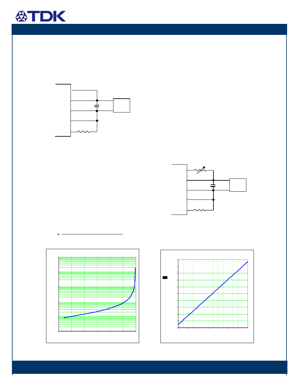
If the output voltage adjustment feature is
not used, the Vout(+) pin should be shorted
to the sense(+) pin and the Vout(-) pin
should be shorted to the sense(-) pin by
jumper wires.
Figure Trim Down Connection
S(+)
Vo(+)
S(-)
Vo(-)
Trim
Load
Rext2
Co
To trim the output voltage down, a fixed or
variable resistor, Rext2, shall be connected
between the trim pin and the sense(-) pin
while the Vout(-) pin and the sense(-) pin are
shorted by a jumper wire. Vout(+) pin and
the sense(+) pin should also be shorted by a
jumper wire as shown below. The resistor,
Rext2, can be chosen according to the
following equation:
Rext2
264.69 Vodown
⋅
1006.785483
−
1081.515138 38.75 Vodown
⋅
−
Trim-down Resistance vs. Vout
1
10
100
1000
10000
100000
16
18
20
22
24
26
28
Output Voltage (V)
T
rim
R
es
ist
an
ce
(
K
Ω
)
In order to trim the output voltage from the
minimum value (-40% down) to the
maximum value (+10% up) in a linear
fashion, a fixed resistor, Rext, should be
connected between the trim pin and the
sense(-) pin while a 50K
Ω variable resistor,
Rv, shall be connected between the Vout(+)
pin and the sense(+) pin as shown below.
When Rext=5.11K
Ω
and
Rv=5.36 K
Ω, the
voltage trim rate is changed to
approximately 0.5V / K
Ω starting from
16.8V. The resistor, Rv, should be chosen
according to the following equation:
Rv
≅ 1.984 × (Vo_d – 14.122) (KΩ)
where Vo_d is the desired output voltage.
Figure Linear Trim Connection
S(+)
Vo(+)
S(-)
Vo(-)
Trim
Load
Rext
Co
Rv
Linear Trim Resistance vs. Vout
4.0
7.0
10.0
13.0
16.0
19.0
22.0
25.0
28.0
31.0
34.0
16.8
18.8
20.8
22.8
24.8
26.8
28.8
30.8
Output Voltage (V)
T
ri
m
R
e
si
st
anc
e (
K
)