Data sheet: maxeta, Ifa series – TDK Maxeta iFA Series User Manual
Page 14
Data Sheet: Maxeta
TM
iFA Series
©2002-2006 TDK Innoveta Inc.
iFA 28V 600W Advance Datasheet 8/3/2006
℡
(877) 498-0099
14/19
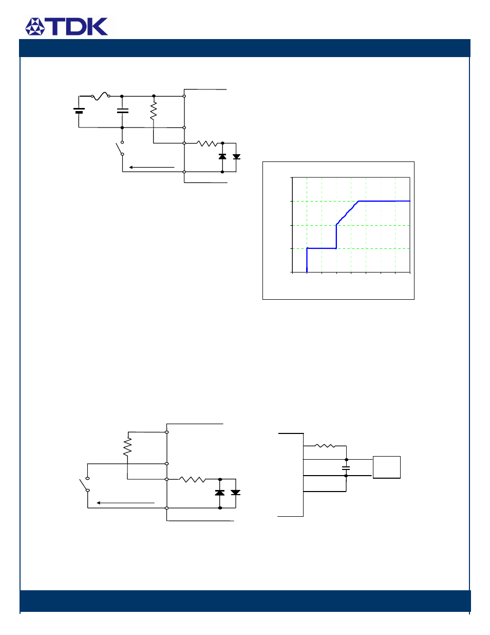
An alternative way to control ON/OFF is
from the output side by utilizing AUX output
pin of the same module. To do so, the user
must supply a switch between the module
sense(-) terminal and the –ON/OFF terminal
of ON/OFF pins. A 2.5 K
Ω, 0.1W resistor is
recommended to connect between the
module AUX pin and the +ON/OFF terminal.
The maximum current sinking capability of
the ON/OFF terminal is 5mA or less. The
current required to maintain the module ON
status must be greater than 1mA.
Other methods such as using an external
power source and a transistor are also
possible. Please consult the field application
engineering department of Innoveta
Technologies for details.
Output Voltage Adjustment: The output
voltage
of the power module is adjustable by
the user using an external resistor or by
applying external voltage. However, when
the output voltage is increased, the input
voltage range is limited as shown in the
following figure.
To trim the output voltage up, a fixed or
variable resistor, Rext1, shall be connected
between the Vout(+) pin and the sense(+)
pin while the Vout(-) pin and the sense(-) pin
should be shorted by a jumper wire as
shown below. The trim pin should be left
open. The output voltage trim-up rate is
approximately 1V / K
Ω. To trim the voltage
up to 30.8V
from 28V, a 2.87K
Ω external
resistor should be used.
S(+)
Vo(+)
S(-)
Vo(-)
Trim
Load
Rext1
Co
Figure Trim up Connection
SW
FUSE
C1
R1
+Vin
-Vin
+ON/OFF
-ON/OFF
I
ON/OFF
ON/OFF Control from Input Side
SW
R1
AUX
-S
+ON/OFF
-ON/OFF
1K
I
ON/OFF
ON/OFF Control from Output Side
Input Limit for Vo,trim
95
100
105
110
115
35
36
37
38
39
40
41
42
43
Vin(V)
V
o,t
rim
(%
V
o,
nom
)