Data sheet: maxeta, Ifa series, Input/output ripple and noise measurements – TDK Maxeta iFA Series User Manual
Page 18: Safety considerations
Data Sheet: Maxeta
TM
iFA Series
©2002-2006 TDK Innoveta Inc.
iFA 28V 600W Advance Datasheet 8/3/2006
℡
(877) 498-0099
18/19
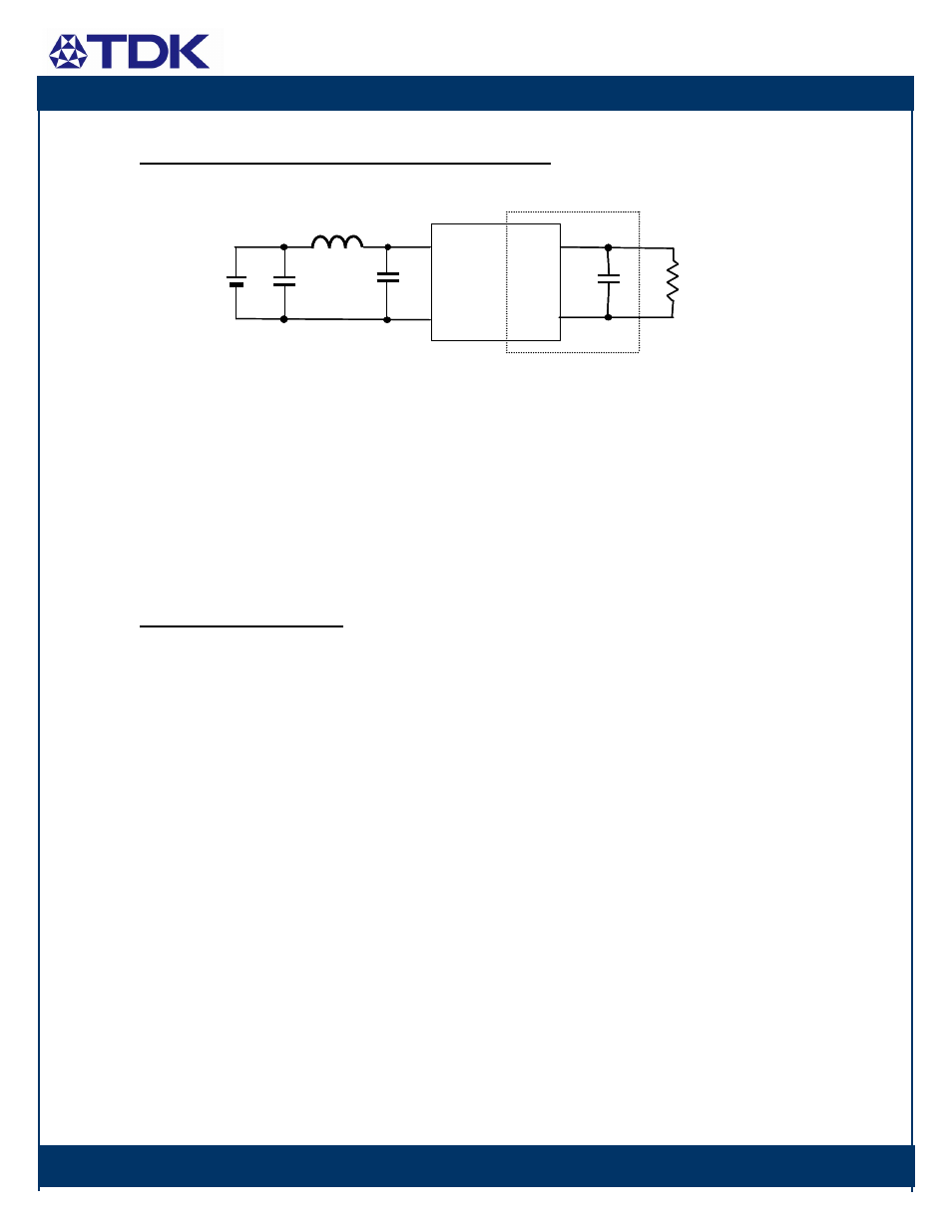
Input/Output Ripple and Noise Measurements:
The input reflected ripple is measured with a current probe and oscilloscope. The ripple current is the current through the
15uH inductor, Lin, with esr
≤ 10 mΩ, feeding a capacitor, C1, esr ≤ 700 mΩ @ 100kHz, across the module input voltage
pins. The capacitor C1 across the input shall be at least 100
µF/100V. A 470µF/100V or two 220µF/100V capacitors in
parallel is recommended. A 220
µF/100V capacitor for C0 is also recommended.
The output voltage ripple measurement is made approximately 5 cm (2 in.) from the power module using an oscilloscope
and BNC socket. The capacitor Cext consisting of a 0.1
µ
F and a 10
µF ceramic capacitors and at least a 470µF or larger
aluminum electrolytic or tantalum capacitor (esr
≤ 300 mΩ) located about 5 cm (2 in.) from the power module. At Io <
Io,min, the module output is not required to be within the output voltage ripple and noise specification.
Safety Considerations:
All TDK Innoveta products are certified to
regulatory standards by an independent,
Certified Administrative Agency laboratory.
UL 1950, 3
rd
edition (US & Canada), and
other global certifications are typically
obtained for each product platform.
The iFA products have the following
certifications:
UL 60950 (US & Canada)
VDE 0805
CB Scheme (IEC 950)
CE Mark (EN60950)
For safety agency approval of the system in
which the DC-DC power module is installed,
the power module must be installed in
compliance with the creepage and clearance
requirements of the safety agency. The
isolation is basic insulation. For applications
requiring basic insulation, care must be
taken to maintain minimum creepage and
clearance distances when routing traces
near the power module.
As part of the production process, the power
modules are hi-pot tested from primary and
secondary at a test voltage of 1500Vdc.
When the supply to the DC-DC converter is
less than 60Vdc, the power module meets
all of the requirements for SELV. If the
input voltage is a hazardous voltage that
exceeds 60Vdc, the output can be
considered SELV only if the following
conditions are met:
1) The input source is isolated from the ac
mains by reinforced insulation.
2) The input terminal pins are not
accessible.
3) One pole of the input and one pole of
the output are grounded or both are kept
floating.
4) Single fault testing is performed on the
end system to ensure that under a
single fault, hazardous voltages do not
appear at the module output.
+
C0
C1
Vout
+
-
-
Lin
Vs
Vin
Cext
R
Load
Ground Plane
+
C0
C1
Vout
+
-
-
Lin
Vs
Vs
Vin
Cext
R
Load
R
Load
Ground Plane