Figure 3–10. class d currents, Figure 3–11. class d voltages – Texas Instruments TPA005D02 User Manual
Page 30
The TPA005D02 Audio Power Amplifier Evaluation Module
3-16
Details
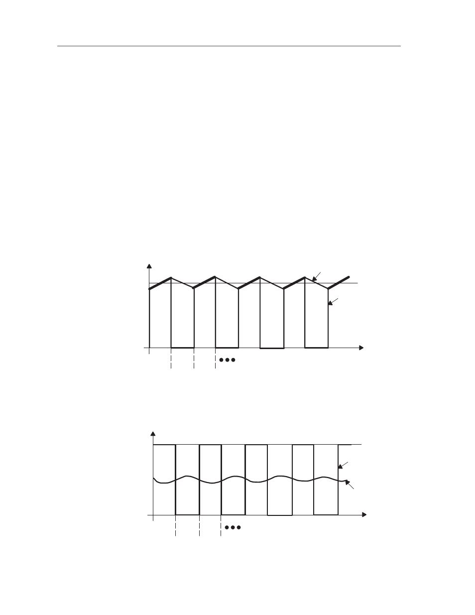
Figures 3–10 and 3–11 show the currents and voltages of the half-bridge
circuit. When transistor M1 is on and M2 is off, the inductor current is
approximately equal to the supply current. When M2 switches on and M1
switches off, the supply current drops to zero, but the inductor keeps the
inductor current from dropping. The additional inductor current is flowing
through M2 from ground. This means that V
A
(the voltage at the drain of M2,
as shown in Figure 3–9) transitions between the supply voltage and slightly
below ground. The inductor and capacitor form a low-pass filter, which makes
the output current equal to the average of the inductor current. The low pass
filter averages V
A
, which makes V
OUT
equal to the supply voltage multiplied
by the duty cycle.
Control logic is used to adjust the output power, and both transistors are never
on at the same time. If the output voltage is rising, M1 is on for a longer period
of time than M2.
Figure 3–10. Class D Currents
Supply Current
Time
M1 on
M2 off
M1 off
M2 on
M1 on
M2 off
Output Current
Inductor Current
0
Current
Figure 3–11. Class D Voltages
VDD
VA
VOUT
0
V
oltage
Time
M1 on
M2 off
M1 off
M2 on
M1 on
M2 off