Texas Instruments TPA005D02 User Manual
Page 23
The TPA005D02 Audio Power Amplifier Evaluation Module
3-9
Details
The transfer function is easily derived by using a voltage divider equation with
the load voltage being a parallel combination of R
L
and C
L
. This transfer
function is
V
O
(s)
V
I
(s)
+
1
LC
L
S2
)
1
R
L
C
L
S
)
1
LC
L
The next step is to set the terms of the circuit transfer function equal to the
terms of the normalized 2nd-order Butterworth low-pass filter and solve for L
and C
L
in terms of R
L
. This yields
C
L
+
1
2
Ǹ
R
L
L
+
2
Ǹ
R
L
These values give a cut-off frequency at
ω
0
= 1 radian/second, which means
that the components must be frequency scaled. To frequency scale, each
component is divided by
ω
0
= 2
×
π
×
f
c
(f
c
is the desired cut-off frequency in
Hertz):
C
SE
+
1
2
Ǹ
R
L
ω0
L
SE
+
2
Ǹ
R
L
w
o
ω
0
+
2
p
fc
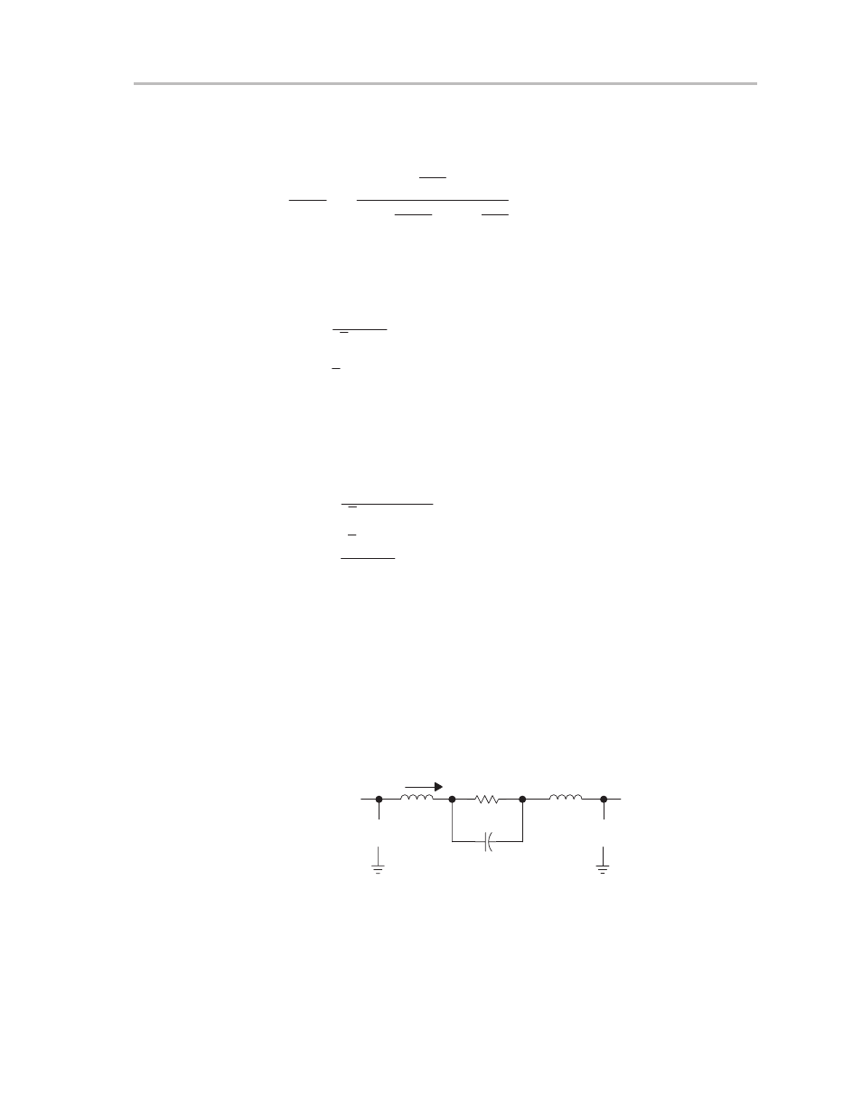
Because the TPA005D02 is a bridged amplifier, this filter is needed at both the
positive and negative output. This means that R
L
must be split between each
filter, so for a bridged application, R
L
must be divided by 2 in the component
calculations. One capacitor can be used in place of the two capacitors in the
output filters if the capacitor is placed across R
L
instead of from each side of
R
L
to ground. This circuit is shown in Figure 3–7.
Figure 3–7. Low-Pass Filter for Bridged Application
IO
RL
CBTL
+ VO –
LBTL
VI
+
–
VI
+
–