Texas Instruments TPA005D02 User Manual
Page 19
The TPA005D02 Audio Power Amplifier Evaluation Module
3-5
Details
3.2.2
Overview of Class D Audio Amplifiers
Class D audio amplifiers are very similar in operation to switch-mode power
supplies in that both compare an input signal with a reference to create an error
voltage that controls a pulse-width modulator (PWM) circuit. The PWM then
produces an output signal at constant frequency and with a duty cycle that
varies according to the input signal. This controls the switching action of the
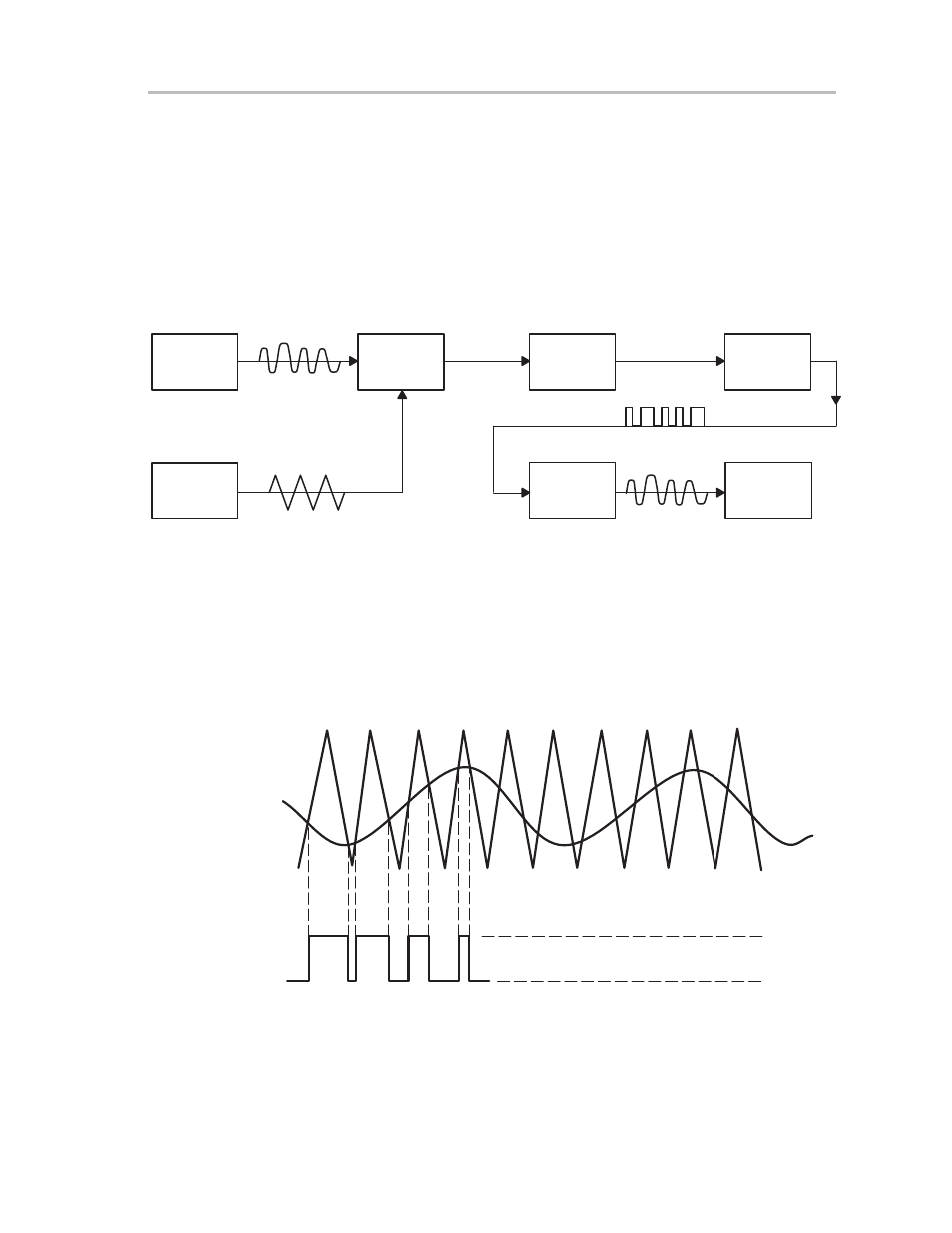
output power stage (H-bridge). A block diagram of the major components that
make up the amplifier is shown in Figure 3–4.
Figure 3–4. Class D Functional Diagram
Audio
Analog
Source
Comparator
VERROR
H-Bridge
LPF
VCONTROL
Load
Ramp
Generator
PWM
Control
VOUT
The audio input signal (V
in
) is applied to a comparator along with a triangle
wave created by the ramp generator (V
ramp
). When the triangle wave crosses
the audio input on the rising and falling ramps, the comparator sends an error
signal to the PWM control circuit. The PWM signal regulates the duty cycle of
the H-bridge circuit to provide V
out
. Examples of these waveforms are shown
in Figure 3–5.
Figure 3–5. Class D Input and Output Waveforms
5 V
0 V
VRAMP
VIN
VOUT
The triangle wave must be operating at a much higher frequency than the
highest frequency component of the input signal in order to get an accurate
representation at the amplifier output. The TPA005D02 EVM uses a 250 kHz
switching rate to sample the input, which is more than ten times higher than
the highest frequency component of the 20 Hz to 20kHz audio input range.