Installation, 1 ups location, 3 ups battery module hardwire connection – Tripp Lite 30kVA User Manual
Page 6: Operation (normal conditions), 1 turning the ups on, 2 turning the ups off, Installation 4. operation (normal conditions)
6
• Press the front “OFF” button. Your load will still be energized. The inverter is now off, but your UPS is not fully
deactivated. The LCD Display will show “ON BYPASS.”
• Turn the AC Input and Bypass AC Input Circuit Breakers OFF. Your load will no longer be energized, and the LCD display
will be dark.
• Make sure the UPS is properly installed (see section 3, Installation) and the Manual Bypass Switch is set to NORMAL.
• Turn the AC Input and Bypass AC Input Circuit Breakers ON.
• If your AC input is providing power normally within your selected range, your connected load will energize in Bypass. However, the
UPS's inverter is not yet on. Press the front “ON” button to begin inverter operation.
• If your AC input is not providing power normally, you have the option of starting from battery. (Your battery must be at least
partially charged for this operation to succeed.) Press and hold both the “Battery Start” switch and the “ON” button for three
seconds to start your UPS in “ON BATTERY” mode. Note that some electronic equipment may draw more amps during startup;
when starting from battery, consider reducing the initial load on the UPS.
• The UPS will perform a brief self-test and show the results on the LCD Display. (See section 4.3, Self-Testing, for display sequence.)
After a successful self-test, the UPS will provide AC power from the inverter to your load.
Warning: When installing the unit, verify that any maintenance bypass panel used is configured correctly before applying power to the
unit.
In addition to the instructions listed below, follow all warnings found in section 1, Important Safety Warnings, prior to connection.
WIRING SELECTION
Choose appropriate cabling (rated VW-1, FT-1 or better) to connect your UPS Power Module to an AC power supply and your equipment.
UPS System Model
Wiring Size
20kVA
6 AWG / 14 mm2
30kVA
4 AWG / 22 mm2
Maximum Cable Length: 10 m (32.8 ft)
WIRING CONNECTION
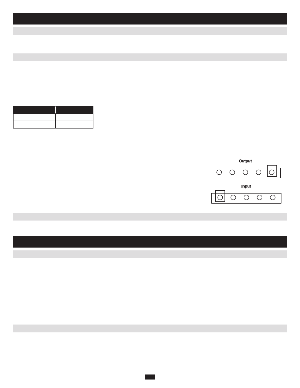
Connect your wiring to the input and output terminal blocks located on the lower rear panel of your UPS (see figure below).
CAUTION!
Qualified personnel should follow all procedures prescribed by N.E.C. and other local codes
for hardwiring devices to a utility source. Ensure that cables are fitted with cable sleeves
and are secured by connector clamps. Tighten connections with a torque of not less than 35
inch-pounds. Observe the appropriate cable connection regulations [e.g. National Electrical
Code (NEC) in the U.S.] at all times. Using cables of improper size may damage your equip-
ment and cause fire hazards.
Note: When shipped from the factory, bypass input and main input wires are connected.
Move your UPS over short distances using its wheels. Stabilize the UPS by releasing the stabilizers on each side of the unit. Note: Do not
stack the UPS System power module or external battery modules.
Refer to the Battery Module's Owner's Manual for all safety warnings and connection instructions.
3.2 UPS Power Module Input And Output Hardwire Connection
3.3 UPS Battery Module Hardwire Connection
3.1 UPS Location
4.1 Turning The UPS On
4.2 Turning The UPS Off
3. Installation
4. Operation (Normal Conditions)
N
2
N
1
T
2
R
1
S
2
S
1
R
2
T
1
G
G
N
2
N
1
T
2
R
1
S
2
S
1
R
2
T
1
G
G