System start up, Pilot valve operation, Troubleshooting – Toro 850S User Manual
Page 4: Pilot valve
System Start Up
_________________________________________________________
The following is a recommended procedure that will protect system components during system start-up. The procedure is based on a
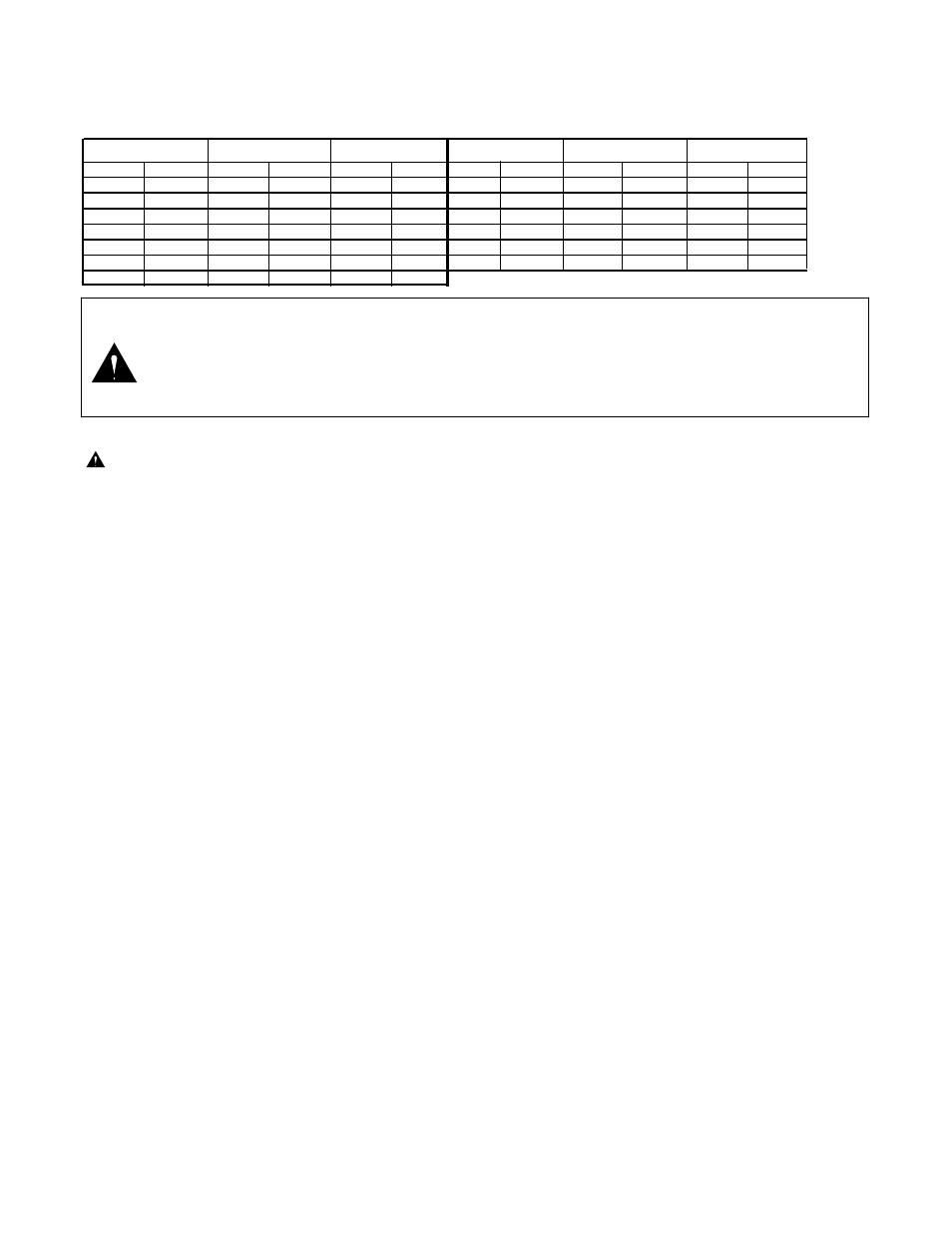
velocity fill rate of less than 2' (.61 m) per second. See Table 3 below.
Table 3: Recommended System Fill Rate
1. Use a jockey pump only to fill the system at a velocity fill rate of less than 2' (0.61 m) per second.
CAUTION: Failure to comply with recommended fill rate will increase line pressure resulting in a water hammer
effect that could damage sprinklers and piping components. See Warning above.
2. At all tees and greens use quick coupler keys with quick coupler valves to bleed air from the system lines during the filling
process. For best results, do not compress air and then relieve it – bleed the air constantly while filling the system.
3. After water has filled all lines and all air is removed, remove the quick coupler keys.
Pilot Valve Operation
(Electric Models Only)
________________________________________
The pilot valve controls the operation of the main valve located in the base of the sprinkler body. The main valve is operated by the release
of water metered through the pilot valve when it is activated either manually at the sprinkler or by the irrigation system controller.
The pilot valve regulates the water pressure to the sprinkler nozzle. Pressure regulation compensates for large variations within the
system and maintains a constant pressure for optimum sprinkler operation. The pilot valve is factory set to regulate one of four
pressure levels: 50 psi (3.4 bar), 65 psi (4.5 bar), 80 psi (5.5 bar) or 100 PSI (6.9 bar).
The sprinkler operation mode is set using a Toro Selector Tool (P/N 995-15) inserted through the body flange onto the pilot valve D-
shaped selector cam. The "AUTO" mode permits automatic operation from the system controller. The "ON" mode opens the main
valve for manual operation and "OFF" mode prevents the main valve from opening.
Troubleshooting
_________________________________________________________
■
Pilot Valve
Possible equipment failures with causes and corrective action are listed below.
PROBLEM
POSSIBLE CAUSE – CORRECTIVE ACTION
SPRINKLER WILL
(a) No 24 VAC to coil assembly. (Electric Models)
NOT TURN ON
– Measure voltage with a Digital Volt Meter (DVM). Check wiring and controller program.
– Refer to Controller Operating Instructions.
(b) Selector cam in "OFF" position.
– Set to "AUTO" position.
(c) Debris in pilot valve assembly.
– Disassemble and remove all debris. (See Servicing Pilot Valve page 11.)
(d) Insufficient pressure in controller supply line and/or sprinkler control tube. (N.C. Models)
– Check pressure.
SPRINKLER WILL
(a) Constant 24 VAC from controller. (Electric Models)
NOT SHUT OFF
– Check for voltage using a DVM. If voltage is present, disconnect wire.
If sprinkler closes, service controller. Refer to Controller Service Manual.
(b) Selector cam in manual "ON" position.
– Set to "AUTO" or "OFF" position.
(c) Debris in pilot valve assembly.
– Disassemble and remove all debris. (See Servicing Pilot Valve page 11.)
(d) Constant pressure from controller. (N.C. Models)
– Check pilot valve at controller for constant flow.
– Check elevation differential. Valve elevation should not exceed 0' above
controller elevation or 70' (21.3 m) below controller elevation.
4
WARNING
NEVER STAND OR LEAN OVER THE SPRINKLER WHILE THE IRRIGATION SYSTEM IS BEING FILLED,
DURING MANUAL OR AUTOMATIC OPERATION OR WHEN PERFORMING SPRINKLER SERVICE
PROCEDURES. DIRECT CONTACT WITH IRRIGATION SPRAY, A FAILED OR IMPROPERLY INSTALLED
SPRINKLER CONNECTION OR SPRINKLER COMPONENTS FORCIBLY EJECTED UPWARD UNDER
PRESSURE CAN CAUSE SERIOUS INJURY.
Pipe Size
Flow
Velocity
Pipe Size
Flow
Velocity
in.
cm
GPM
LPM
ft/sec
m/sec
in.
cm
GPM
LPM
ft/sec
m/sec
1/2
1.3
2
7.6
1.60
0.49
3
7.6
45
170.3
1.86
0.57
3/4
1.9
3
11.4
1.92
0.59
4
10.1
75
283.9
1.87
0.57
1
2.5
5
18.9
1.50
0.46
6
15.2
150
567.8
1.73
0.53
1-1/4
3.1
10
37.9
1.86
0.57
8
20.2
250
946.3
1.70
0.52
1-1/2
3.8
10
37.9
1.41
0.43
10
25.4
450
1703.0
1.97
0.60
2
5.0
20
75.7
1.80
0.55
12
30.5
500
1893.0
1.55
0.47
2-1/2
6.4
30
113.6
1.84
0.56