Important le canada seulement – TOA Electronics SSDV-3328 User Manual
Page 35
35
NOTE: DIAGRAMS & ILLUSTRATIONS NOT TO SCALE.
Note - use extra care not to engage the
orifice strip with the 7/16" open end wrench
(contacting the orifice strip could cause strip
distortion rendering the pilot inoperative).
Also avoid wrench contact to any of the
other pilot parts.
Use a 7/16" open end wrench and turn the
pilot hex fitting counter-clockwise 1/4 turn.
(See Figure 62 ).
Note - The orifice strip tab may be randomly
located on any side of the hex fitting.
d. Push the orifice strip tab all the way
against the hex fitting to align the appropri-
ate gas type orifice (see Figures 61 & 62 ).
The type of gas for which the pilot is set,
is, the gas type shown on the tab.
e. Retighten, clockwise, the pilot hex
fitting until the pilot hood aligns with the
thermocouple and thermopile as indicated
by the arrows shown in Figure 62.
Adjusting Knob
Conversion screw
(blue natural gas;
red LP/propane gas)
Regulator Cap
Honeywell Millivolt Gas Valve
Figure 60
Pilot for Honeywell Millivolt Gas Valve
Figure 61
b. Attach manometer to the manifold side
pressure test fitting and verify manifold
pressure reads 3.5 inches water column
(0.87 kPa) for natural gas, and 10.0
inches water column (2.49 kPa) for pro-
pane gas.
c. Convert the pilot orifice as follows (see
Figures 61 & 62):
b. Attach manometer to the manifold side
pressure test fitting and verify manifold
pressure reads 3.5 inches water column (0.87
kPa) for natural gas, and 10.0 inches water
column (2.49 kPa) for propane gas.
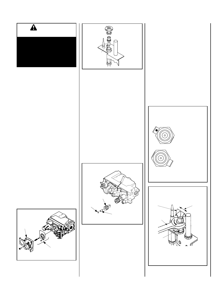
c. Refer to Figure 59 and remove the pilot
hood assembly to access the hexed pilot orifice.
Remove and replace the orifice with the one
provided with the kit.
Step 5. Millivolt Appliances
Honeywell Systems -
a. Convert the gas valve as follows
(see Figure 60): Remove the plastic protecting
cap. Remove the gas type setting screw by
turning it counterclockwise. Obtain the replace-
ment gas type setting screw from the kit and
screw it into place (red for propane and blue
for natural gas). Tighten the gas type setting
screw by turning it clockwise. Replace the
plastic protecting cap.
Pilot for Honeywell Millivolt Gas Valve
(Loosening of Hex Fitting For
Orifice Strip Tab Positioning)
Figure 62
7/16 in. Open
End Wrench
Hood
Hood
Alignment
Orifice
Strip Tab
Take care not to contact the orifice strip tab
with the hex fitting wrench - distortion of the
tab may render the pilot inoperative.
LP (propane) Gas Posi-
tion - 1/16 inch hole,
LP and red color shown
on tab.
Natural Gas Position
- NAT shown on tab.
Top View of Hex Fiting and Orifice Strip Tab
Orifice Strip Tab Position Identification
For LP (propane gas) and Natural Gas
P
L
NA
T
SIT Millivolt Gas Valve
Pilot for SIT Millivolt
Gas Valve
Pressure
Regulator
Remove
These
Components
Figure 58
Pilot
Orifice
Gas conversion kits are available to adapt the
appliance from the use of one type of gas to
the use of another. These kits contain all the
necessary components needed to complete the
task including labeling that must be affixed to
ensure safe operation.
Kit part numbers are listed here and the following
steps detail the conversion procedure.
Step 1. Turn off the gas supply to the appliance.
Remove the front glass door/frame from the
appliance. Access the control compartment.
Step 2. Carefully remove the logs. Exercise care
so as not to break the logs.
Step 3. Locate the screws securing the burner
assembly to the appliance. Remove the burner
assembly and retain the securing screws.
Step 4. Millivolt Appliances - SIT Systems
a. See Figure 58 and the instructions
provided with the kit. Using a Torx T20,
tool or or standard flat screwdriver remove
and discard the three pressure regulator
mounting screws. Remove the pressure
regulator, spring, poppet, diaphragm and
bushing. Discard all removed components.
Ensure the rubber gasket installed on the
back of the replacement pressure regulator
is properly positioned and install the new
pressure regulator using the new screws
supplied with the kit. Tighten screws to 25
In. lb. torque.
IMPORTANT
LE CANADA SEULEMENT
La conversion devra être effectuée
conformément aux recommanda-
tions des autorités provinciales
ayant juridiction et conformément
aux exigences du code d'installation
CAN1-B149.1 ET.2.
Figure 59