Table 11, Effective vent length – TOA Electronics SSDV-3328 User Manual
Page 14
14
NOTE: DIAGRAMS & ILLUSTRATIONS NOT TO SCALE.
SV4.5CGV-1
Termination
SV4.5FA OR
SV4.5FB Flashing
AND SV4.5SC
STORM COLLAR
�
SV4.5VF
Firestop/Spacer
SV4.5L6/12/24/36/48
Vent Sections
40' Max
(12.2 M)
1" (25.4 mm)
Minimum
Clearance to
Combustibles
�
When using Secure Flex
use Firestop/Spacer
SF4.5VF
T
R
A
H
C
H
T
G
N
E
L
N
O
I
T
C
E
S
T
N
E
V
n
o
it
c
e
S
l
a
n
i
m
o
N
)
s
e
h
c
n
i(
h
t
g
n
e
L
6
2
1
4
2
6
3
8
4
T
O
T
A
L
Q
T
Y
n
o
it
c
e
S
t
e
N
)
s
e
h
c
n
i(
h
t
g
n
e
L
2
/
1
-
4
2
/
1
-
0
1
2
/
1
-
2
2
2
/
1
-
4
3
2
/
1
-
6
4
t
n
e
V
f
o
t
h
g
i
e
H
s
n
o
it
c
e
S
t
n
e
V
f
o
r
e
b
m
u
N
s
e
h
c
n
i
tf
4
4
1
2
1
1
0
0
0
3
4
0
5
1
5
.
2
1
0
1
0
0
3
4
5
.
4
5
1
5
7
8
.
2
1
1
1
0
0
3
5
5
.
0
6
1
5
7
3
.
3
1
0
2
0
0
3
5
5
.
2
7
1
5
7
3
.
4
1
0
0
0
5
0
5
7
7
1
5
7
.
4
1
1
0
0
5
0
6
3
8
1
5
2
.
5
1
0
1
0
5
0
6
6
8
1
5
.
5
1
0
0
0
0
4
4
5
.
0
9
1
5
7
8
.
5
1
1
0
0
0
4
5
5
.
6
9
1
5
7
3
.
6
1
0
1
0
0
4
5
5
.
5
0
2
5
2
1
.
7
1
0
1
1
5
0
7
7
0
2
5
2
.
7
1
0
0
0
6
0
6
5
.
1
1
2
5
2
6
.
7
1
1
0
0
6
0
7
5
.
7
1
2
5
2
1
.
8
1
0
1
0
6
0
7
5
.
9
2
2
5
2
1
.
9
1
0
0
1
6
0
7
5
.
2
3
2
5
7
3
.
9
1
0
0
0
0
5
5
7
3
2
5
7
.
9
1
1
0
0
0
5
6
5
.
1
4
2
5
2
1
.
0
2
0
0
0
7
0
7
6
4
2
5
.
0
2
1
0
0
7
0
8
2
5
2
1
2
0
1
0
7
0
8
4
6
2
2
2
0
0
1
7
0
8
6
7
2
3
2
0
0
0
8
0
8
9
7
2
5
2
.
3
2
0
0
0
0
6
6
5
.
0
8
2
5
7
3
.
3
2
1
0
0
8
0
9
5
.
3
8
2
5
2
6
.
3
2
1
0
0
0
6
7
5
.
9
8
2
5
2
1
.
4
2
0
1
0
0
6
7
5
.
1
0
3
5
2
1
.
5
2
0
0
1
0
6
7
5
.
0
1
3
5
7
8
.
5
2
0
0
0
9
0
9
5
1
3
5
.
6
2
1
0
0
9
0
0
1
5
.
5
2
3
5
2
1
.
7
2
0
0
0
0
7
7
0
3
3
5
.
7
2
1
0
0
0
7
8
6
3
3
8
2
0
1
0
0
7
8
5
4
3
5
7
.
8
2
0
0
0
0
1
0
0
1
5
.
9
4
3
5
2
1
.
9
2
1
0
0
0
1
0
1
1
2
7
3
1
3
0
0
0
0
8
8
5
.
6
7
3
5
7
3
.
1
3
1
0
0
0
8
9
5
.
9
7
3
5
2
6
.
1
3
0
0
0
1
1
0
1
1
5
.
8
1
4
5
7
8
.
4
3
0
0
0
0
9
9
3
2
4
5
2
.
5
3
1
0
0
0
9
0
1
5
6
4
5
7
.
8
3
0
0
0
0
0
1
0
1
VENT SECTION LENGTH CHART
Nominal Section
Length (inches)
6
12
24
36
48
Net Section
Length (inches)
4 ½
10 ½
22 ½
34 ½
46 ½
Height of Vent
Number of Vent Sections
*inches
feet
T
O
T
A
L
Q
T
Y
T
R
A
H
C
H
T
G
N
E
L
N
O
I
T
C
E
S
T
N
E
V
l
a
n
i
m
o
N
h
t
g
n
e
L
n
o
it
c
e
S
)
s
e
h
c
n
i(
6
2
1
4
2
6
3
8
4
T
O
T
A
L
Q
T
Y
n
o
it
c
e
S
t
e
N
)
s
e
h
c
n
i(
h
t
g
n
e
L
2
/
1
-
4
2
/
1
-
0
1
2
/
1
-
2
2
2
/
1
-
4
3
2
/
1
-
6
4
t
n
e
V
f
o
t
h
g
i
e
H
s
n
o
it
c
e
S
t
n
e
V
f
o
r
e
b
m
u
N
s
e
h
c
n
i
tf
5
.
4
5
7
3
.
0
1
0
0
0
0
1
9
5
7
.
0
2
0
0
0
0
2
5
.
0
1
5
7
8
.
0
0
1
0
0
0
1
5
1
5
2
.
1
1
1
0
0
0
2
5
.
9
1
5
2
6
.
1
2
1
0
0
0
3
1
2
5
7
.
1
0
2
0
0
0
2
5
.
2
2
5
7
8
.
1
0
0
1
0
0
1
5
.
5
2
5
2
1
.
2
1
2
0
0
0
3
5
.
1
3
5
2
6
.
2
0
3
0
0
0
3
5
.
4
3
5
7
8
.
2
0
0
0
1
0
1
5
.
7
3
5
2
1
.
3
1
1
1
0
0
3
5
.
3
4
5
2
6
.
3
0
2
1
0
0
3
5
4
5
7
.
3
0
0
2
0
0
2
5
.
6
4
5
7
8
.
3
0
0
0
0
1
1
5
.
9
4
5
2
1
.
4
1
0
2
0
0
3
1
5
5
2
.
4
1
0
0
0
1
2
5
.
5
5
5
2
6
.
4
0
1
2
0
0
3
7
5
5
7
.
4
0
0
1
1
0
2
6
6
5
2
.
5
0
2
2
0
0
4
5
.
7
6
5
2
6
.
5
0
0
3
0
0
3
9
6
5
7
.
5
0
0
0
2
0
2
2
7
6
1
0
3
0
0
4
5
.
3
7
5
2
1
.
6
1
0
0
2
0
3
5
.
9
7
5
2
6
.
6
0
1
0
2
0
3
1
8
5
7
.
6
0
0
0
1
1
2
0
9
5
.
7
0
2
1
0
1
4
5
.
1
9
5
2
6
.
7
0
0
2
0
1
3
3
9
5
7
.
7
0
0
0
0
2
2
6
9
8
1
0
1
2
0
4
5
.
7
9
5
2
1
.
8
1
0
0
0
2
3
2
0
1
5
.
8
2
0
0
0
2
4
5
.
3
0
1
5
2
6
.
8
0
0
0
3
0
3
8
0
1
9
1
0
0
3
0
4
4
1
1
5
.
9
0
2
0
0
2
4
7
1
1
5
7
.
9
1
0
5
0
0
6
5
.
8
1
1
5
7
8
.
9
1
1
0
3
0
5
6
2
1
5
.
0
1
0
0
1
3
0
4
5
.
0
3
1
5
7
8
.
0
1
1
0
1
3
0
5
5
3
1
5
2
.
1
1
0
0
6
0
0
6
8
3
1
5
.
1
1
0
0
0
4
0
4
5
.
9
3
1
5
2
6
.
1
1
0
0
0
0
3
3
5
.
2
4
1
5
7
8
.
1
1
1
0
0
4
0
5
VENT SECTION LENGTH CHART
Nominal
Section Length
(inches)
6
12
24
36
48
Net Section
Length (inches)
4 ½
10 ½
22 ½
34 ½
46
½
Height of Vent
Number of Vent Sections
*inches
feet
T
O
T
A
L
Q
T
Y
Table 10a
Table 10b
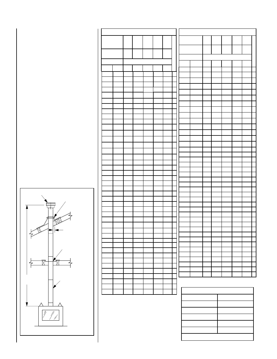
Figure 18
VERTICAL TERMINATION SYSTEMS (ROOF)
Figure 21 (Page 15), and Figures 26 to
30 (Pages 17 and 18) and their associated
Vertical Vent Tables illustrate the various verti-
cal venting configurations that are possible for
use with these appliances. Secure Vent pipe
applications are shown in these Figures; Secure
Flex pipe may also be used. A Vertical Vent
Table summarizes each system’s minimum and
maximum vertical and horizontal length values
that can be used to design and install the vent
components in a variety of applications.
Both these vertical vent systems terminate
through the roof. The minimum vent height
above the roof and/or adjacent walls is speci-
fied in ANSI Z223.1-(latest edition) (In Canada,
the current CAN-1 B149 installation code) by
major building codes. Always consult your lo-
cal codes for specific requirements. A general
guide to follow is the Gas Vent Rule (refer to
Figure 5 on Page 7).
Vertical (Straight) Installation
Determine the number of straight vent sections
required. 4-1/2" (114 mm), 10-1/2" (267 mm),
22-1/2" (572 mm), 34-1/2" (876 mm) and 46-
1/2" (1181 mm) net section lengths are available
(see Table 11 and Page 32 - Item 3). Plan the
vent lengths so that a joint does not occur at
the intersection of ceiling or roof joists. Refer
to the Vent Section Length Chart.
* Convert inches into metric equiva-
lent measure, as follows:
Millimeters (mm) = Inches x 25.4
Centimeters (cm) = Inches x 2.54
Meters (M) = Inches x .0254
Effective Vent Length
Model
Effective Length
SV4.5L6
4-1/2"
SV4.5L12
10-1/2"
SV4.5L24
22-1/2"
SV4.5L36
34-1/2"
SV4.5L48
46-1/2"
Table 11