TOA Electronics SSDV-3328 User Manual
Page 28
28
NOTE: DIAGRAMS & ILLUSTRATIONS NOT TO SCALE.
Figure 51
3/8" to 1/2"
(9 -13 mm)
Hot Surface
Igniter
Proper Flame
Adjustment
Pilot
Nozzels
ELECTRONIC PILOT ASSEMBLY
Proper Pilot Flame Appearance
Electronic Appliance Checkout
To light the burner, turn ‘ON’ the optional remote
wall switch and turn the gas control switch to
the “ON” position. Ensure the Igniter lights the
pilot. The pilot flame should engulf the flame
rod as shown in Figure 51.
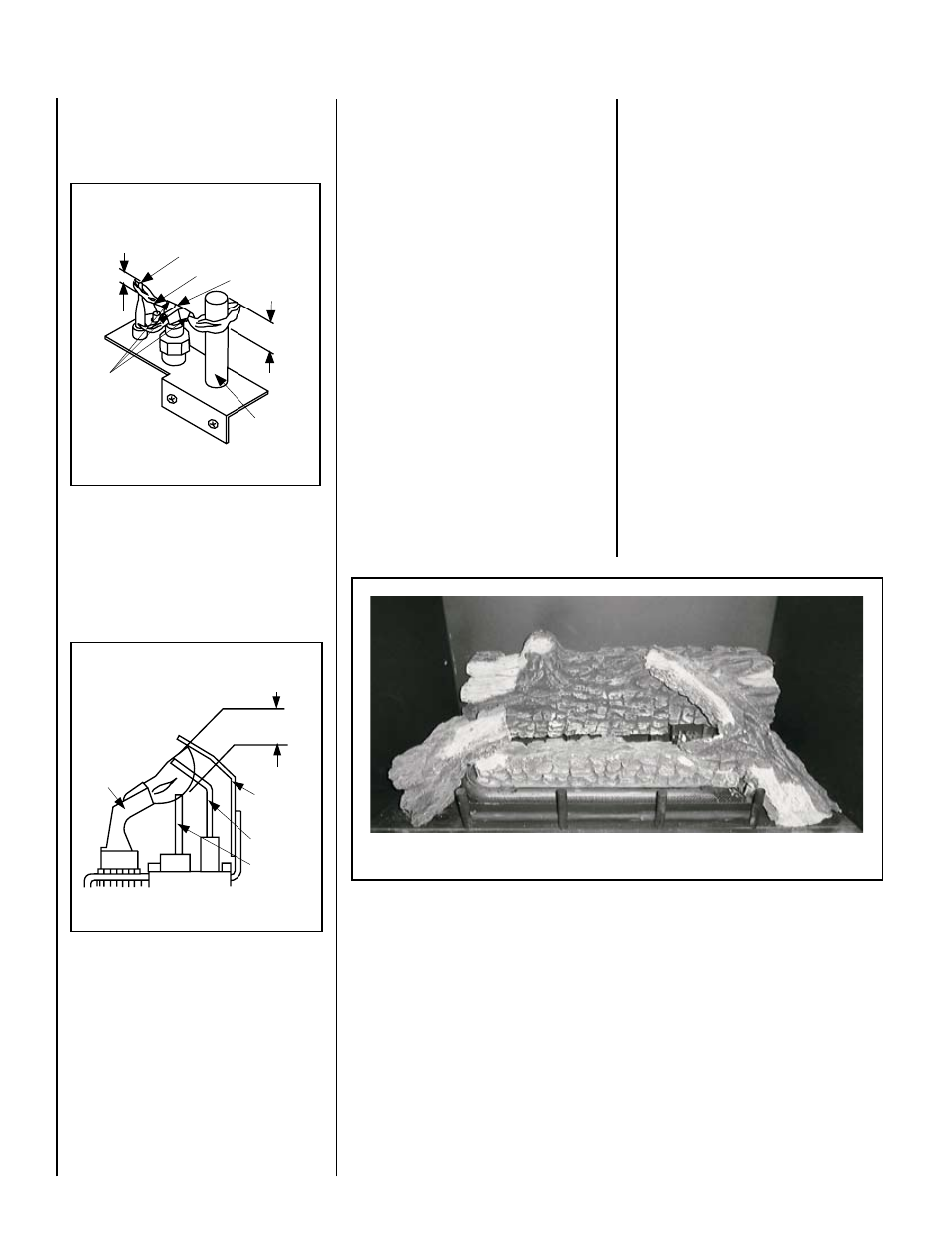
INSTALL LOGS, VOLCANIC STONE AND
GLOWING EMBERS
Carefully position the ceramic fiber logs and
twigs over the burner according to the following
steps, while referring to Figure 52.
1. Set the rear log on the raised log support
brackets at the rear of the firebox, fitting
the slots in the log over the brackets.
2. Position the front log with the pins for the
two side twigs in the up position, and the
two vertical burner tabs recessed into the
two notches at the rear of the log. Check
for recessing of brackets into log notches
(by touch) to verify correct log placement.
3. Insert the alignment hole of the left twig over
the front log's left pin. Rotate the left twig
until it just touches the edge of the ember
bracket.
4. Insert the alignment hole of the right twig
over the front log's right pin. Rotate the
right twig until it almost touches the front
panel glass.
Note: Proper twig placement is critical in the
gaps between the flame peaks and should be
positioned so that at no time they impinge
the flames.
Glowing Ember/Volcanic Stone Placement
Remove the replacement rockwool (Glowing
Embers) from the packaging and tear into
quarter size pieces (see Figure 53 ).
Spread rockwool (quarter-sized pieces) on and
along the length of the burner screen. Do not
use more than is necessary. To many quarter-
sized pieces on the front burner section will
cause poor combustion.
When properly positioned, the rockwool will
unevenly cover approximately 85% of the
burner screen, with no appreciable gaps or
openings.
To install Decorative Volcanic Stone, mound up
a portion of the volcanic stone in front of the
burner in a pattern to suite individual taste.
Figure 52 -
Log Set (Shown With Optional Log Rack)
Replace logs if removed for pilot inspection.
To light the burner; turn “ON” the remote wall
switch and rotate the gas valve control knob
counterclockwise to the “ON” position.
Figure 50
Proper Pilot Flame Appearance
Thermocouple
Thermopile
Pilot
Nozzels
1/8" Min.
(3 mm)
Igniter Rod
Hood
HONEYWELL MILLIVOLT PILOT ASSEMBLY
3/8" Min.
(9 mm)