Pin assignment of computer in terminals, Specifications, Continued) – Toshiba TDP-FF1A User Manual
Page 46
46
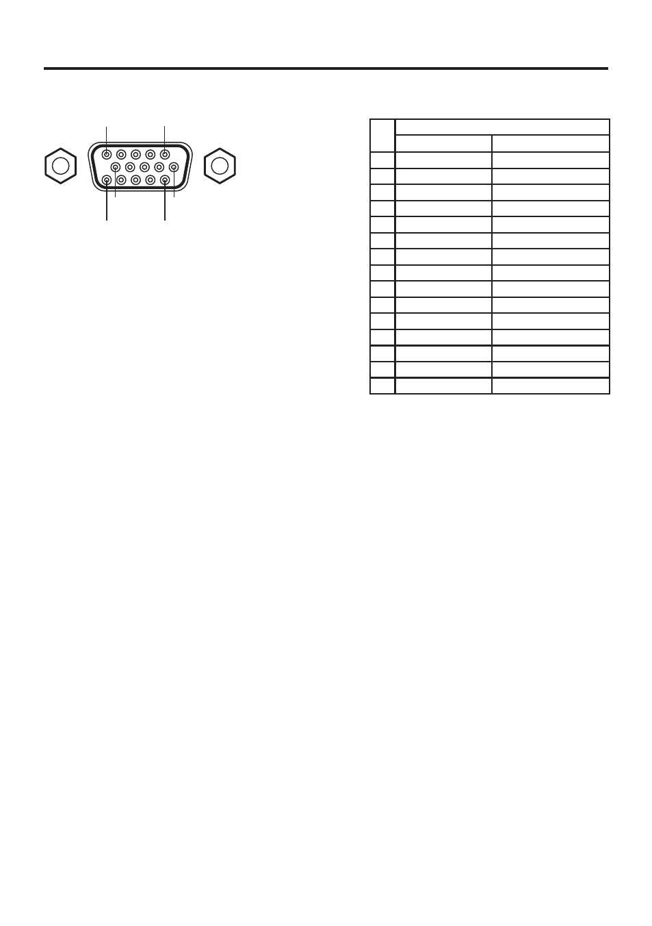
Pin assignment of COMPUTER IN terminals
11
15
6
1
5
10
Input Signal
• RGB input
RGB signals:
0.7V (p-p) 75 Ω
Horizontal sync signal: TTL level (Pos/neg polarity)
Vertical sync signal: TTL level (Pos/neg polarity)
• Y/P
B
/P
R
input
Y signal:
1.0V (p-p) 75 Ω
P
B
/P
R
signals:
0.7V (p-p) 75 Ω
Mini D sub 15 Pin connector
Pin
No.
Pin description
During RGB input
During Y/PB/PR input
1
Video signal (R)
Color difference signal (P
R
)
2
Video signal (G)
Luminance signal (Y)
3
Video signal (B)
Color difference signal (P
B
)
4
N.C
∗
5
GND
∗
6
GND (R)
GND (P
R
)
7
GND (G)
GND (Y)
8
GND (B)
GND (P
B
)
9
+5V
∗
10 GND
∗
11 N.C
∗
12 SDA
∗
13 Horizontal sync signal
∗
14 Vertical sync signal
∗
15 SCL
∗
∗ Do not connect anything.
Specifications
(continued)
See also other documents in the category Toshiba Projectors:
- 65NH84 (68 pages)
- TXP451 (9 pages)
- 46H84 (64 pages)
- 57HM117 (74 pages)
- TLP511U (47 pages)
- 62HM195 (112 pages)
- TDP-D2 (20 pages)
- TDP-T90 (25 pages)
- TP 50H60 (63 pages)
- 72MX195 (136 pages)
- T620 (37 pages)
- Camileo TDP-S20 (25 pages)
- 62HM84 (68 pages)
- Data TDP-T420 (29 pages)
- 43H72 (56 pages)
- 53AX62 (2 pages)
- TXP650 (52 pages)
- MP8640 (30 pages)
- PROJECTORS (8 pages)
- TLP260 (78 pages)
- TLP780E (80 pages)
- DLP 46HM95 (112 pages)
- TLF-XD2000 (28 pages)
- TDP-T100 (28 pages)
- TLP-B2U (67 pages)
- 56HM66 (56 pages)
- TLP 261 (2 pages)
- MP8745 (39 pages)
- Integrated High Definition DLP Projection Televison 62HM196 (92 pages)
- TDP-TW90A (37 pages)
- 57HX94 (2 pages)
- COLORSTREAM SRS TOUCHFOCUS 57H84C (64 pages)
- TDP-S9 (43 pages)
- TDP-T91 (25 pages)
- t90 (2 pages)
- TDP-P75 (45 pages)
- T501U Series (2 pages)
- TDP-T90U (2 pages)
- TDP-TW420U (1 page)
- TDP-TW300 (1 page)
- P503DL (41 pages)
- TDP-TW90 (37 pages)
- G 3 (2 pages)
- 51H93 (100 pages)
- Projector-Laptop (5 pages)