41dvn / dvsn direct vent gas fireplace, Remote controls, Ceramic refractory panels – Temco Tool 41DVN User Manual
Page 47: Decorative bay windows, Decorative frame trim, Remote on/off switch
47
41DVN / DVSN Direct Vent Gas Fireplace
20009999
Remote Controls
Optional remote control units are available to control
different functions of the appliance.
Model Functions Controlled
RC1
ON/OFF
RC2
ON/OFF and Temperature
IMTFK Wall mounted thermostat control
Ceramic Refractory Panels
Ceramic refractory panels are available to line the fire-
box area.
Unit
Kit Model
41DV DV360CR
Take care when handling the refractory
panels as they are fragile until held in
place and supported.
Installation Instructions
1. Remove window frame assembly and logs.
2. Remove three (3) screws securing heat shield to
combustion dome. (Fig. 65)
3. Place rear ceramic panel in back of unit.
4. Place side panels.
5. Replace heat shield, logs and window frame assem-
bly.
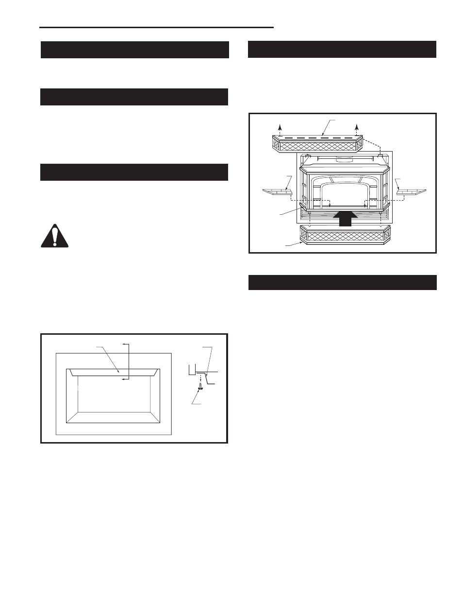
Decorative Bay Windows
Installation
Remove the existing louvre assembly top.
Assemble the Bay Window Kit according to the instruc-
tions supplied with the kit. (Fig. 66)
FP1194
Install bay
window
2/19/02 djt
Upper Grille Assembly
Ceramic
Refractory
Ceramic
Refractory
Window As-
sembly
Base Grille As-
sembly
FP1194
Fig. 66 Bay window.
H103
heat shield
3/1/99 djt
Heat Shield
Section A
Heat
Shield
(3)
Screws
Side View
Section A
H103
Fig. 65 Heat shield.
Decorative Frame Trim
A selection of decorative frame trim kits are available
for mounting around the outside of the appliance to en-
hance its visual effect on the room. Installation instruc-
tions for each decorative frame trim are included with
the frame trim kit. Contact your authorized distributor for
details of the trim kits and ordering information for the
trim kits applicable to this model appliance.
Remote ON/OFF Switch
The optional ON/OFF Switch Kit (53875) allows the fire-
place to be turned on or off from a remotely located wall
switch. Installation instructions begin on Page 8.