41dvn / dvsn direct vent gas fireplace, Vertical sidewall installation twist lock pipe – Temco Tool 41DVN User Manual
Page 19
19
41DVN / DVSN Direct Vent Gas Fireplace
20009999
X
X
FP1181
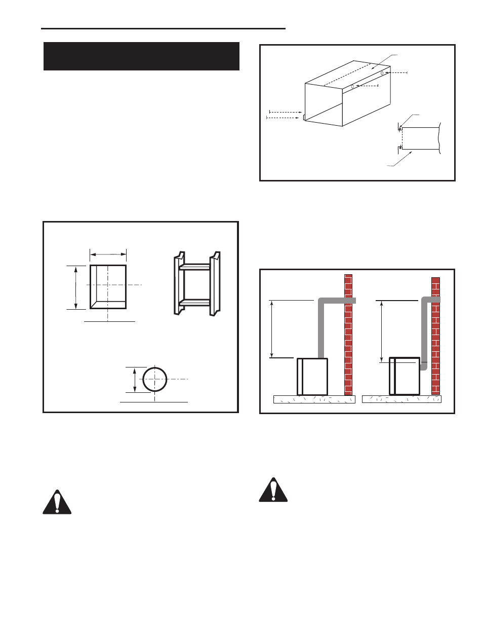
Fig. 33 Vertical height requirements.
Vertical Sidewall Installation
Twist Lock Pipe
Step 1
Locate vent opening on the wall. It may be necessary
to first position the fireplace and measure to obtain hole
location. Depending on whether the wall is combustible
or noncombustible, cut opening to size. (Fig. 31) (For
combustible walls first frame in opening.)
NOTE: When using flex vent, the opening will have to
be measured according to the 1/2” (13 mm) rise in 12”
(305 mm) vent run.
Combustible Walls: Cut a 9³⁄₈”H x 9³⁄₈”W (240 x 240
mm) hole through the exterior wall and frame as shown.
(Fig. 31)
Noncombustible Walls: Hole opening must be 7¹⁄₂”
(191 mm) in diameter.
ZCS101
Zero Clearance Sleeve
3/11/99 djt
#8 Screws
(2)
Adjustable Zero Clearance Sleeve
Firestop
#8 Screws (2)
#8 Screws (2)
Adjustable Zero Clear-
ance Sleeve
Max. Length 12”
(305mm)
Fig. 32 Adjustable zero clearance sleeve.
ZCS101
Zero clearance sleeve is only required for
combustible walls.
Fig. 31 Locate vent opening on wall.
VO584-100
Vent Opening
2/99 djt
9³⁄₈"
(240mm)
Vent Opening for Combustible Wall
Fireplace Hearth
Framing Detail
7¹⁄₂" Dia.
(190mm)
Vent Opening Noncombustible Wall
9³⁄₈"
(240mm)
Fireplace Hearth
VO584-100
Step 4
Apply a band of silicone to the inner and outer flue
collars of the fireplace and using appropriate length of
pipe section(s) attach to fireplace with three (3) screws.
Follow with the installation of the inner and outer elbow,
again secure joints with three (3) sheet metal screws.
Wipe off any excess high temperature sealant.
Step 2
Measure wall thickness and cut zero clearance sleeve
parts to proper length (MAXIMUM 12” / 305 mm).
Assemble sleeve and attach to firestop with #8 sheet
metal screws (supplied). Install firestop assembly. (Fig.
32)
Step 3
Place fireplace into position. Measure the vertical height
(X) required from the base of the flue collars to the cen-
ter of the wall opening. (Fig. 33)
Step 5
Measure the horizontal length requirement including a
2” (51 mm) overlap, i.e. from the elbow to the outside
wall face plus 2” (51 mm) (or the distance required if
installing a second 90° elbow). (Fig. 34)
Always install horizontal venting on a level
plane.
Step 6
Use appropriate length of pipe sections - telescopic or
fixed - and install. The sections which go through the
wall are packaged with the starter kit, and can be cut to
suit if necessary.