Characteristics, Ip 67 monobloc i/o splitter boxes for fieldbuses, Advantys – Quantum Instruments Splitter Boxes User Manual
Page 26: Distributed i/o, ftb splitter boxes, Environmental characteristics, Fieldbus characteristics
26
Characteristics
0
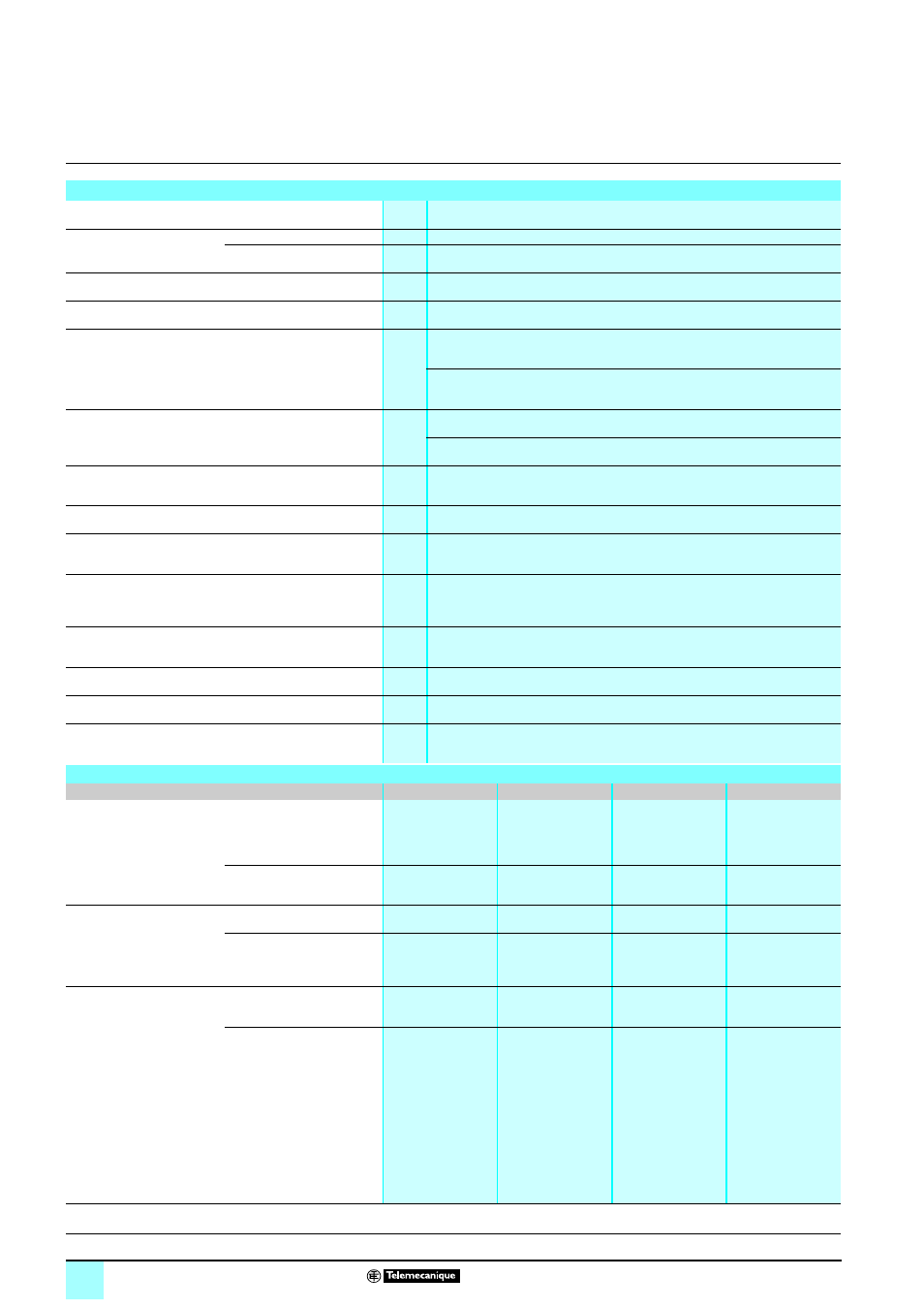
IP 67 monobloc I/O splitter boxes
for fieldbuses
0
Advantys™
Distributed I/O, FTB splitter boxes
Environmental characteristics
Product certifications
cULus
Temperature
Operation
°C (°F)
0 to + 55 (+ 32... 131)
Storage
°C (°F)
- 25 to + 70 (-13...+ 158)
Degree of protection
Conforming to IEC 60529
IP 67
Altitude
m (ft.)
0 to 2000 (0 to 6562)
Vibration resistance
Conforming to IEC 68-2-6,
test Fc
Hz
For plastic housing
5
≤ f ≤ 57.55 (constant amplitude = 1.5 mm)
57.55
≤ f ≤ 500 (constant acceleration = 10 gn)
For metal housing
5
≤ f ≤ 70 (constant amplitude = 1.5 mm)
70
≤ f ≤ 500 (constant acceleration = 15 gn)
Shock resistance
Conforming to IEC 68-2-27,
test Ea
For plastic housing
30 gn, for 11 ms
For metal housing
50 gn, for 11 ms
Resistance to electrostatic
discharge
Conforming to IEC 61000-4-2
kV
Contact:
± 4
Air:
± 8
Resistance to radiated fields
Conforming to IEC 61000-4-3
V/m
10
Immunity to fast transient
currents
Conforming to IEC 61000-4-4
kV
Power supply:
± 2
Signal:
± 2
Surge withstand
Conforming to IEC 61000-4-5
V
Power supply: (symmetrical)
± 500, (asymmetrical) ± 1000
Signals: (symmetrical)
± 500, (asymmetrical) ± 1000
Ground/PE:
± 500
Immunity to conducted
disturbance
Conforming to IEC 61000-4-6
Vrms
10
Resistance to magnetic
fields, 50 Hz
Conforming to IEC 61000-4-8
A/m
30
Mounting
All positions
Mechanical mounting
Mounting by two M4 screws for plastic housing (tightening torque 1.5 Nm / 13.3 lbf-in)
Mounting by two M6 screws for metal housing (tightening torque 9 Nm / 79.7 lbf-in)
Fieldbus characteristics
Bus type
CANopen
DeviceNet
Profibus-DP
InterBus
Structure
Type
EN 50325
ISO 11898
EN 50325
ISO 11898
CAN, layer 7
DeviceNet
DIN 19245
EN 50170
DIN 19258
EN 50254
Access method
Multimaster, priority
information
Master-Slave
Master-Slave,
Multi-Master
Master-Slave
Transmission
Binary rate
1 Mbits/s
500 kbits/s
12 Mbits/s
500 kbits/s
Medium
2 twisted, shielded
wires
4 twisted, shielded
wires
2 twisted, type A,
shielded wires
(RS 485)
3 twisted pairs with
common shielding
Fiber optic
Configuration
Maximum number of devices
127
63
32 without repeater
126 with repeaters
256
Maximum length of bus
At 1 Mbits/s:
- Max. tap-off length:
0.3 m (0.98 ft.)
- Max. cumulative
tap-off length: 1.5 m
(4.9 ft.)
At 500 kbits/s:
- Max. tap-off length:
6 m (19.7 ft.)
- Max. cumulative
tap-off length: 30 m
(32.8 ft.)
Main line:
- 500 m (1640 ft.)
without repeater,
- 3 km (9843 ft.)with
repeater
Tap-off:
6 m (19.7 ft.) max.
Without repeater:
At 12 Mbits/s:
- 100 m (328.1 ft.)max.
At 1.5 Mbits/s:
- 200 m (656.2 ft.)max.
At 500 kbits/s:
- 400 m (1312 ft.)max.
At < 93.75 kbits/s:
- 1.2 km (3937 ft.)max.
Main bus link
(long distance bus):
12.8 km (41,999 ft.)
Local bus link:
50 m (164 ft.)
Presentation, functions:
pages 14 - 17
Description, configuration:
pages 18 , 21, 24,
References:
pages 28 - 30
Dimensions:
pages 31 - 33
Courtesy of Steven Engineering, Inc. ● 230 Ryan Way, South San Francisco, CA 94080-6370 ● General Inquiries: (800) 670-4183 ● www.stevenengineering.com