Optional equipment – Omni Group GREEN SMART 864 User Manual
Page 67
Optional Equipment
(for qualified installers only)
67
© Travis Industries
4090507
100-01217_000
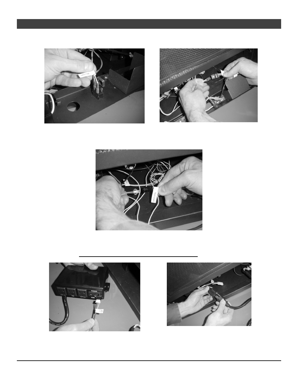
13 Attach the blue and white wires to the IPI/CPI switch (see Figure 19). Connect the wiring
harness to the stepper motor (see Figure 20).
Figure 19
Figure 20
14 Attach the wiring harness to the comfort control valve connection (see Figure 21).
Figure 21
15 Place the fan controller near the front of the fireplace to the left and connect it to the wiring
harness (see Figure 22). Attach the power cord from the fan controller to the AC connection (see
Figure 23). MAKE SURE TO TURN THE FAN CONTROLLER ON (“-“ SYMBOL).
Figure 22
Figure 23