26 installation, Top vent configuration with horizontal termination, For qualified installers only) – Omni Group GREEN SMART 864 User Manual
Page 26
26 Installation
(for qualified installers only)
© Travis Industries
4090507
100-01217_000
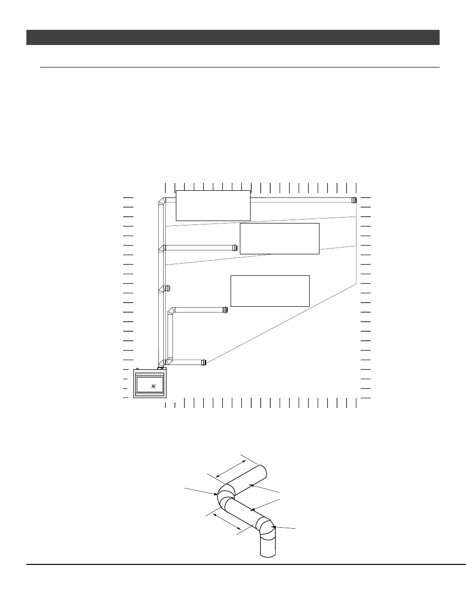
Top Vent Configuration with Horizontal Termination
•
The termination must fall within the shaded area shown in the chart. Use the indicated restrictor and diffuser
positions.
•
Up to four elbows (45° or 90°) may be used.
•
May use 8" (203mm) or 6-5/8" (168mm) diameter vent (see page for 18 details).
•
Only one horizontal elbow may be used.
5 feet (1.5m)
0 feet
0 feet
5 feet (1.5m)
0 feet
20 feet (6m)
20 feet (6m)
5 feet (1.5m)
10 feet (3m)
5 feet (1.5m)
10 feet (3m)
0 feet
15 feet (4.5m)
20' max (6m)
10 feet (3m)
15 feet (4.5m)
15 feet (4.5m)
20' max (6m)
10 feet (3m)
15 feet (4.5m)
21' max (6.4m)
21' max (6.4m)
Exhaust Restrictor # 2
Intake Restrictor # 1 (stock)
Diffuser Position # 2 (stock)
Exhaust Restrictor # 4
Intake Restrictor # 2
Diffuser Position # 2 (stock)
Exhaust Restrictor # 4
Intake Restrictor # 1 (stock)
Diffuser Position # 2 (stock)
This is considered a horizontal
elbow (it does not matter
whether it turns right or left).
It may be a 90° or 45° elbow.
This is considered a
vertical elbow
Horizontal length is calculated by adding
both lengths of horizontal run
(Horizontal Length = H1 + H2).
H1
H2