Installation, Optional wall switch or thermostat installation, For qualified installers only) – Omni Group GREEN SMART 864 User Manual
Page 17: Parallel connection series connection
Installation
(for qualified installers only)
17
© Travis Industries
4090507
100-01217_000
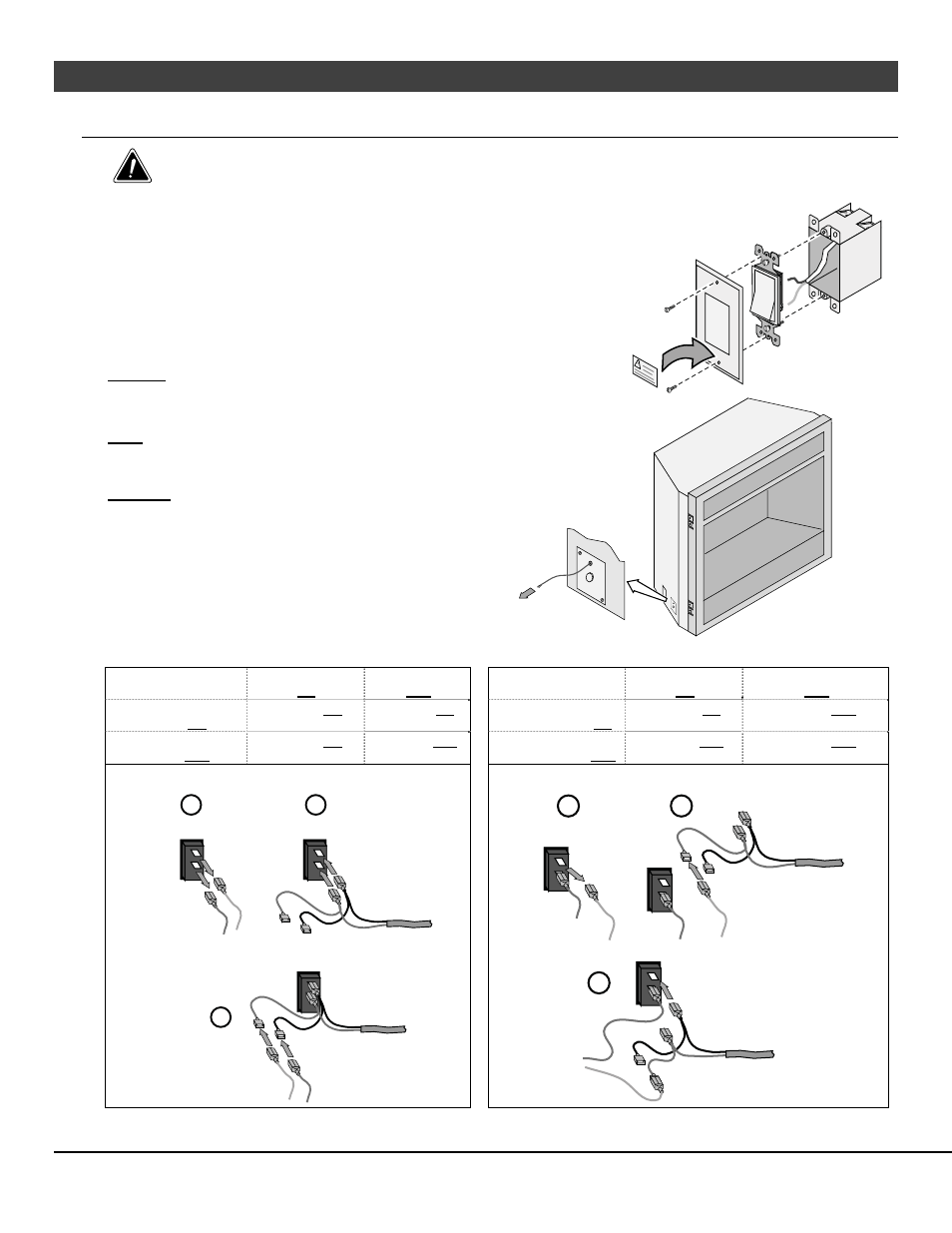
Optional Wall Switch or Thermostat Installation
Do not connect 110-120 VAC to the gas control valve or wiring system of this fireplace. The switch and
wiring must be installed by a qualified installer.
This fireplace includes an optional wall switch (with wire)
to operate the fireplace burner without accessing the
internal on/off switch. A thermostat may be used instead.
Route the wire from inside the fireplace, through the
grommet on either side of the fireplace near the gas inlet
(see at right) to the switch. The wall switch (or thermostat)
may bypass the fireplace on/off switch or be installed in
parallel or series configuration (see below).
Caution
: Label all wires prior to disconnection when
servicing controls. Wiring errors can cause
improper and dangerous operation.
Note
:
When using a GreenSmart™ remote, use the
receiver for on/off operation (do not use a wall
switch or thermostat).
Warning
: Make sure all wiring is secure and does not
contact hot or moving components.
OPTIONAL WALL SWITCH
(included with fireplace)
Place "WARNING"
label on switch cover.
Parallel Connection
Series Connection
On / Off Switch
ON
On / Off Switch
OFF
On / Off Switch
ON
On / Off Switch
OFF
Thermostat / External
Switch ON
Heater is ON
Heater is ON
Thermostat /
External Switch ON
Heater is ON
Heater is OFF
Thermostat / External
Switch OFF
Heater is ON
Heater is OFF
Thermostat /
External Switch OFF
Heater is OFF
Heater is OFF
To wire the heater in parallel, follow the directions below: To wire the heater in series, follow the directions below:
Thermostat
(or External Switch) Wires
a
b
c
On / Off Switch
a
On / Off Switch
c
b
Thermostat
(or External Switch) Wires