Rena DA615 User Manual
Page 21
Addressing media
\text\etd\DA615/address
3.6
DA615 instruction manual
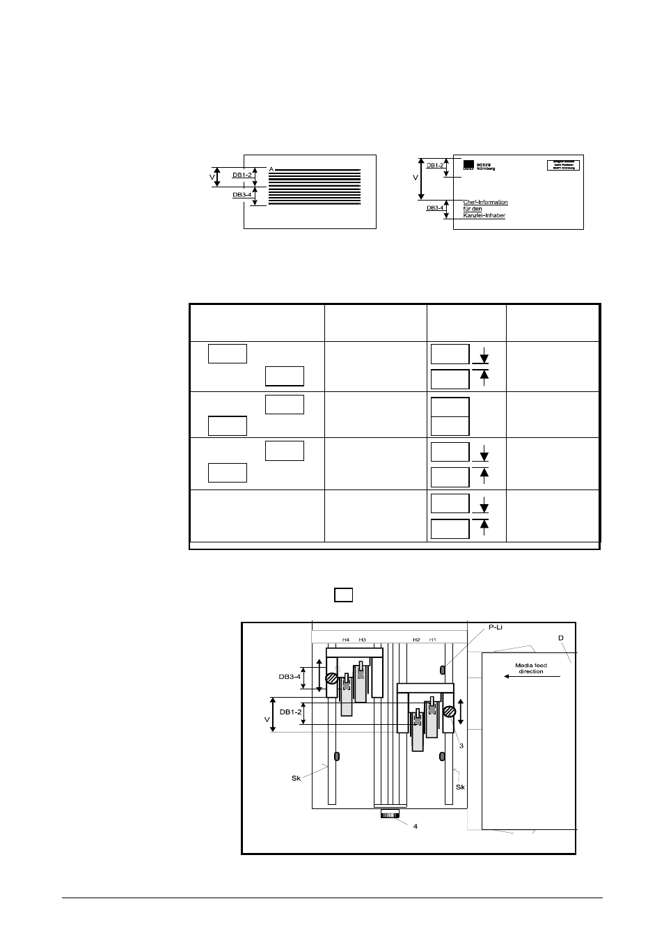
If you want to use the two print areas separately (cf. right-hand diagram below), you
must make sure that a specific minimum offset (V) exists between the print-head
pairs in order to prevent the contact rollers smudging the ink or any overlap of the
print formats.
12-line print format
Two individual print formats
There are several ways of adjusting the print-head pairs. The following table shows
how each offset affects the distance between the print formats.
Arrangement of print-
head pairs
Minimum offset V
Position of
print formats
Distance (a)
between print
formats
H4-H3
H2-H1
38 mm / 1½ inch
DB3-4
DB1-2
12.7 mm /
½ inch
H2-H1
H4-H3
25.4 mm / 1 inch
DB1-2
DB3-4
0 mm / inch
(= 12 line
print)
H2-H1
H4-H3
64 mm / 2½ inch
DB1-2
DB3-4
38 mm /
1½ inch
At any scale end-
positions
175 mm / 7 inch
DB3-4
DB1-2
150 mm /
6 inch
To shift the print-head pairs, loosen fixing screw (3).
You may have to use rotary knob (4) to reduce the pressure of the contact bars on
the transport rollers (cf. page 3.2).
a
a
a