Int/rcv mode, Figure b-3, Int/rcv mode on – RAD Data comm ASM-20 User Manual
Page 57: Figure b-4, B.4 int/rcv mode, Figure b-3. ir-g.703 ext mode timing block, Figure b-4. ir-g.703 int/rcv mode timing block
ASM-20 Installation and Operation Manual
Appendix B IR-G.703 Codirectional Interface (64 kbps)
INT/RCV Mode
B-3
Timing Source
TX Data
TX
TX
RX
RX
RX Data
G.703
Codirectional
64 kbps network
FIFO
EXT Clock Mode
RCV Clock Mode
Clock In
Clock
Out
Modem A
Modem B
Clock
Recovery
Data
Data
CLK
Clock
Recovery
FIFO
IR-G.703 Module
Clock
Recovery
Figure B-3. IR-G.703 EXT Mode Timing Block
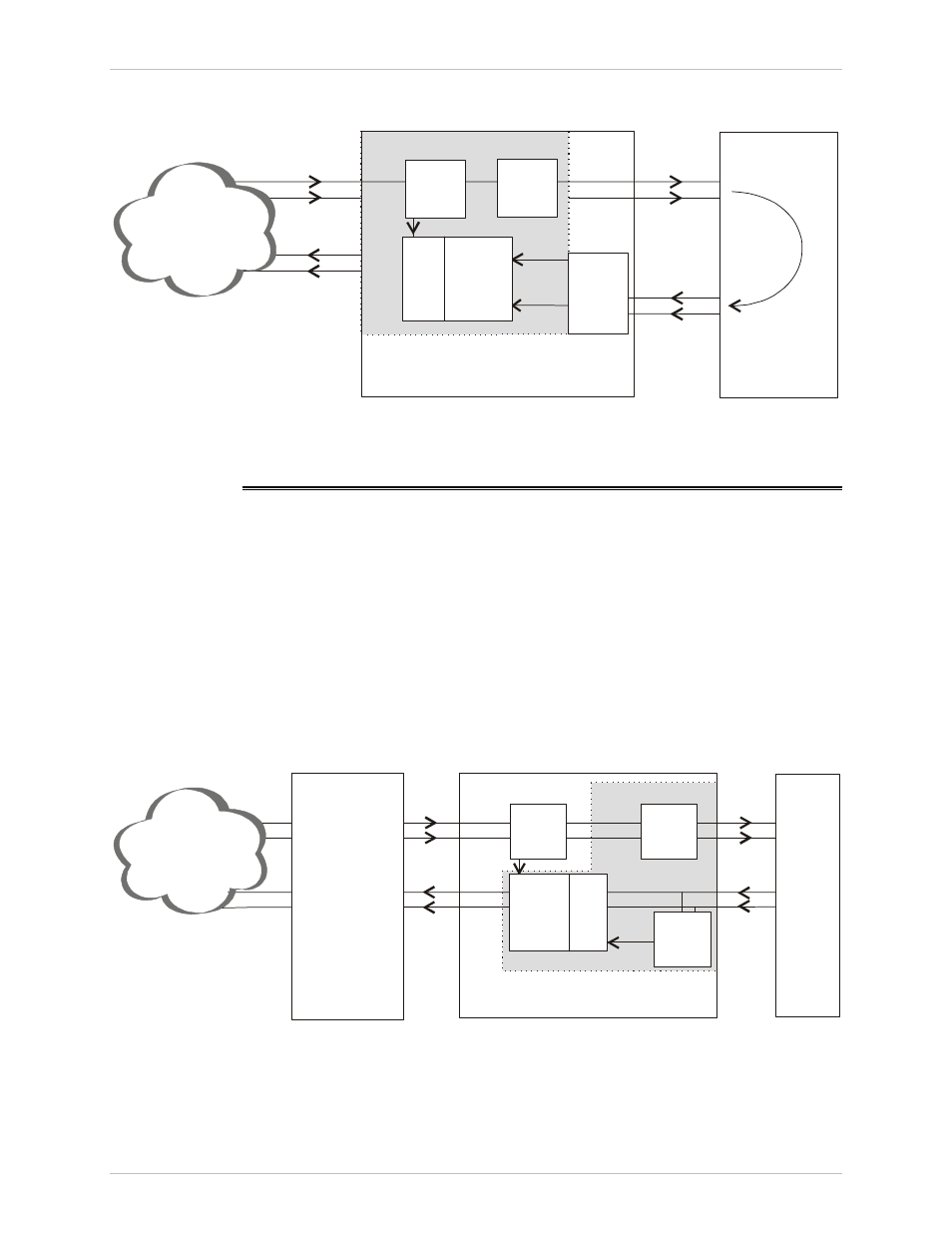
B.4 INT/RCV
Mode
This mode is used in applications where the G.703 codirectional 64 kbps
equipment connected to the modem recovers the clock signal from the modem
link. This mode is used mainly when the attached equipment has a G.703
codirectional interface, but is not able to produce clock signals. The module has a
8-bit FIFO buffer to compensate for the phase delay introduced by the G.703
device.
illustrates the buffer connection and the required application
setup.
This mode corresponds to the modem clock working in the INT or RCV mode.
TX
RX
RX Data
TX Data
TX
RX
INT or RCV
Clock Mode
EXT, INT or RCV
Clock Mode
(Depending on the
attached network)
Modem A
Equipment
with G.703
interface
LINK
side
G.703
side
DTE
side
INT/RCV Clock Mode
Modem B
Clock In
Clock
Out
IR-G.703 Module
Data
Clock
Recovery
FIFO
Clock
Recovery
Data
CLK
FIFO
Figure B-4. IR-G.703 INT/RCV Mode Timing Block