3 setting the switch, Caution, Cautions for setting the switch – Renesas PCA7413F-80 User Manual
Page 9
( 9 / 20 )
3.3 Setting the Switch
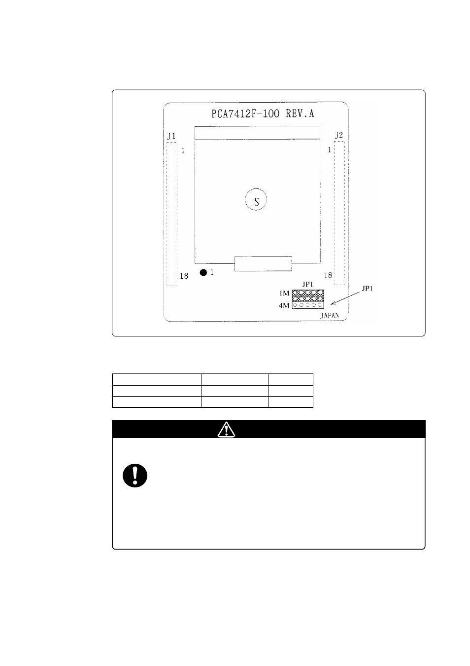
The position of the JP1 and its default setting are shown in Figure 3.2. For how to set the switch, see
Table 3.1.
Figure 3.2 Position of the JP1 switch
Table 3.1 Setting the JP1 switch
Top view
CAUTION
Cautions for Setting the Switch:
• Make the setting properly, because an incorrect setting can cause fatal damage to the
MCU.
• Select the proper programming mode of the PROM programmer.
• An example setting shown in Figure 3.2 is also applied to the PCA7412L-100,
PCA7412G-100, and PCA7413F-80.
• To use this product in M27C201 mode, set the JP1 switch to the 1M side.
Group
Example
JP1
Other than M16C/6V
M30612E4-XXXFP
1M
M16C/6V
M306V2EEFP
4M
This manual is related to the following products: