Installation, Mechanical installation, Electrical installation – Raypak LONMARK Y-200 User Manual
Page 6: Check your power source
6
INSTALLATION
If the controller was not mounted on the boiler by the
factory, care should be taken to select a suitable
mounting location. The controller should be mounted
on a solid and permanent base. The unit should be
readily accessible for maintenance and installation
purposes, and should be mounted so that the display
is at a height and location convenient for viewing.
Mechanical Installation
Install the controller within 30 feet of the boiler(s). It
must be mounted vertically with the conduit holes fac-
ing downward. The conduit holes are sized to
accommodate standard 1/2" conduit fittings. If addi-
tional or larger conduit fittings are required, locate the
conduit connections on the bottom of the module.
Slave units, if present, should be installed adjacent to
the master unit. (Y-304 slave cable is approximately
five feet long.)
Mount the controller using the mounting bracket and
appropriate hardware in four (4) places.
A minimum of eighteen (18) inches clearance from the
front, and six (6) inches clearance on all other sides is
required for service access. The hinged right side of
the box should be installed with sufficient clearance
(minimum 3” from bolt hole on the right side) to open
the cover.
An electrical distribution sub-panel containing appro-
priate disconnect switches and surge suppressors is
required at or near the equipment location(s).
Electrical Installation
Requires: 120 VAC, Draws 0.5 amp; 60 Hz.
120 VAC Feeder Circuits: Install a surge protection
device sized appropriately for your installation at each
module.
Install a separate disconnect means for each load.
Use appropriately sized wire for equipment as defined
by NEC and/or local code. All primary wiring should be
no less than 125% of minimum rating.
It is strongly recommended that the controller and the
boiler(s) be supplied from the same power source.
Install conduit as appropriate.
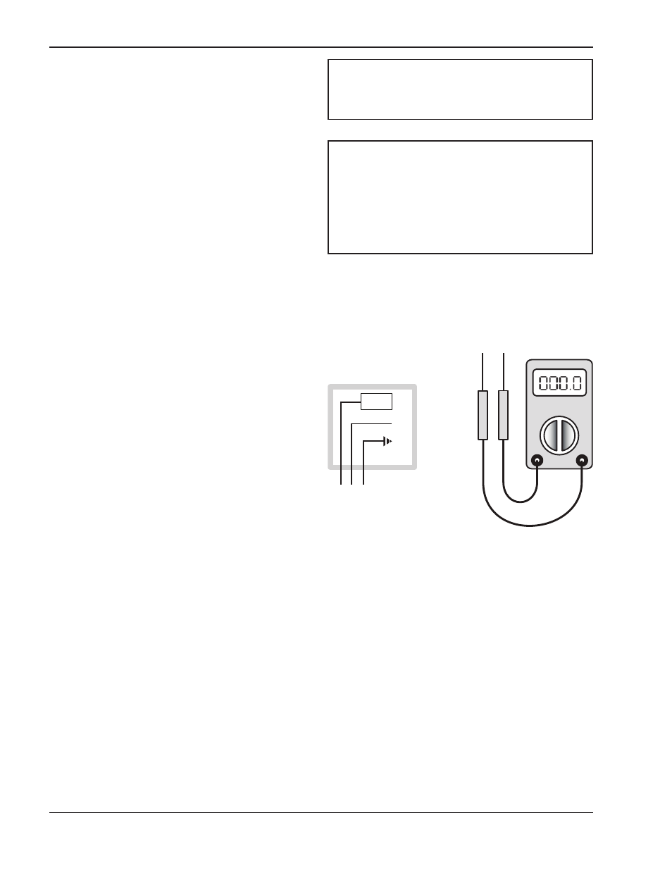
Check Your Power Source
Using a Volt-ohm meter, check the following voltages
at the terminal block inside the unit:
AC = 108 Volts AC Minimum, 132 Volts MAX
AB = 108 Volts AC Minimum, 132 Volts MAX
BC = Must be less than .6 Volts AC
NOTE: Shielded 18 (AWG) gauge stranded wire
must be used to connect the sensors to the
controller. The shielded cable should be protected by
conduit whenever possible.
CIRCUIT
BREAKER
WHITE
GROUND
BLACK
GREEN
A B C
VOLT-OHM
METER
Fig. 1: Volt-ohm Meter
NOTE: Minimum 18 AWG, 105°C, stranded wire
must be used for all low voltage (less than 30 volts)
external connections to the unit. Solid conductors
should not be used because they can cause
excessive tension on contact points. Install conduit
as appropriate. All high voltage wires must be the
same size (105°C, stranded wire) as the ones on the
unit or larger.