Plumbing for water connections – Raypak Versa 105B User Manual
Page 15
PLUMBING FOR WATER CONNECTIONS
LOCATION
The VERSA heater requires water flow and positive
pressure to fire and operate properly. It must therefore be
installed downstream of the discharge side of the filter
pump. A typical installation is plumbed as follows:
1. The inlet side of the filter is plumbed directly to
the discharge side of the filter pump;
2. The outlet side of the filter is then plumbed to
the inlet of the heater; and
3. The outlet of the heater is plumbed to the
return line to the pool or spa. The pump, filter
and heater are thus plumbed in series.
Plumbing from the heater back to the pool must not have
any valves or restriction that could prevent flow when the
pump is operating. To do so will void the warranty.
FLOW RATES
MIN.GPM: 20, MAX.GPM: 115*
*When flow rates exceed 115 GPM an external auxiliary
bypass valve is required. See External Auxiliary Bypass
Valve section for details.
15
COMPANION FLANGE CONNECTIONS
DO NOT use petroleum base assembly fluids (such
as Petroleum Jelly or lubricating oil). If assembly lube is
required use a silicone base such as Amoral etc.
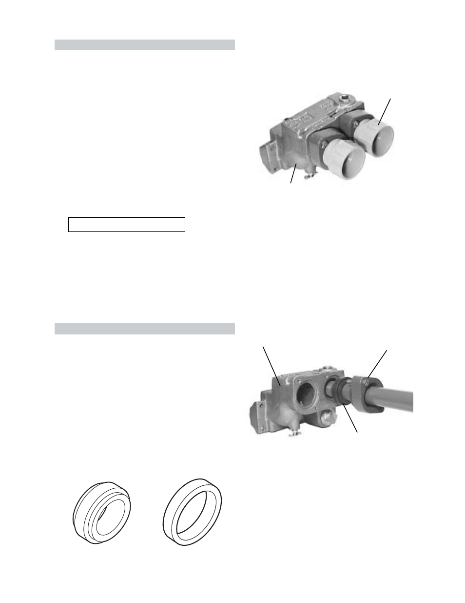
PREMIUM BRONZE HEADER
The inlet/outlet single header flanges are designed for four
type of water connections. There are two sets of flange
gaskets supplied with your header; one set installed,
between flanges and in/out header, and the other set
shipped loose in the unit. Use the appropriate gasket
design, for all your heater connections.
GASKET DESIGN #1: (Factory Installed) Accepts
1-1/2" copper tube or 1-1/4" galvanized pipe as a slip
connections.
GASKET DESIGN #2: (Loose in a Bag) Accepts 2"
copper tube as a slip connection. The flange is threaded
for 2" screw in pipe connections. Also used with the 2"
CPVC adapters.
#1
#2
Fig. #8095.1
Fig. # 8097.1
INLET/OUTLET HEADER
AUTOMATIC CHLORINATORS AND CHEMICAL
FEEDERS
All chemicals must be introduced and completely
diluted into the pool or spa water before being circulated
through the heater. Do not place chlorine tablets or
bromine sticks in the skimmer. High chemical concen-
trations will result when the pump is not running (i.e.
overnight).
Chlorinators must feed downstream of the heater and
have an anti-siphoning device to prevent chemical back-
up into the heater when the pump is shut off.
Fig # 9272
FLANGE GASKET
HEADER FLANGE
Fig # 9273
CAUTION: NEVER install PVC directly in header
flanges. Use the 2" CPVC adapter (supplied by others).
NOTE: If 2" piping is used in the heater, this piping must
be anchored (copper) or screwed into the flange (metal)
if operating pressures above 30 PSI are encountered.
CAUTION: Never install PVC directly in header flanges.
The initial connection must be made with high
temperature materials such as CPVC or copper.
For IID pilots: PVC may be utilized immediately after the
initial connections.
For Standing pilots: Copper or high temperature CPVC
pipe and two elbows are required between the heater and
the PVC connections (heat sinks not supplied).
High temperature 2" plastic pipe (CPVC) may be
threaded directly into the header flanges. This is not the
same as the Schedule 80 PVC pipe which is also colored
gray. PVC may be used immediately after the CPVC
adapters.
INLET/OUTLET HEADER
2" CPVC Adapters
(supplied by others)