Chapter 6. user circuitry, Switches, Leds – Renesas SH7201 User Manual
Page 11: Potentiometer
Chapter 6. User Circuitry
6.1. Switches
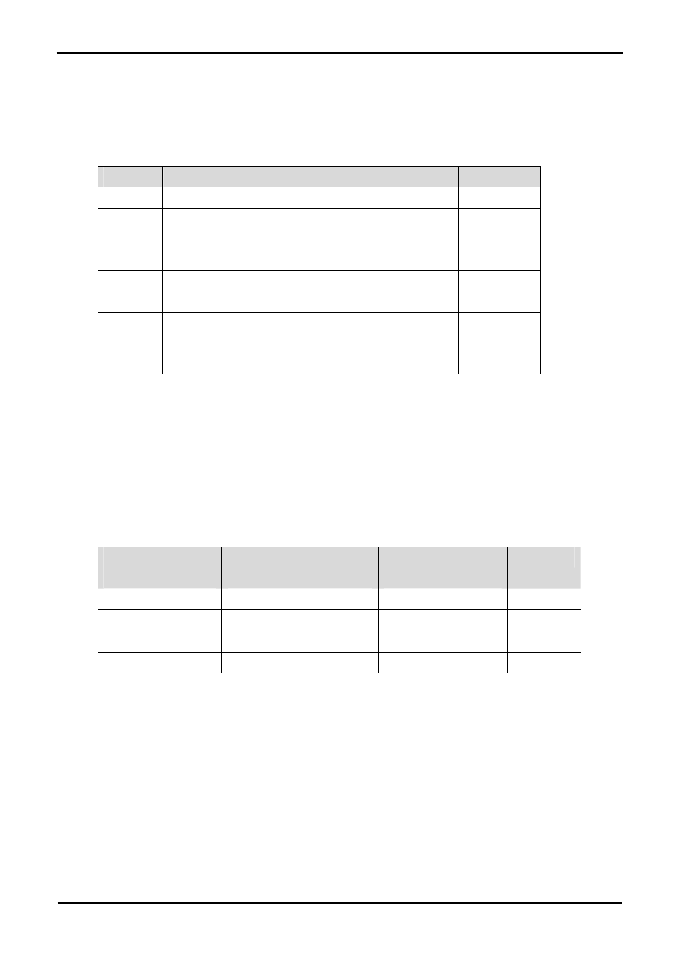
There are four switches located on the CPU board. The function of each switch and its connection are shown in Table 6-1.
Switch
Function
Microcontroller
RES
When pressed; the CPU board microcontroller is reset.
RESn, Pin 2
SW1/BOOT* Connects to an IRQ input for user controls.
The switch is also used in conjunction with the RES switch to place
the device in BOOT mode.
IRQ0, Pin 59
(Port C, bit 22 )
SW2*
Connects to an IRQ line for user controls.
IRQ1 , Pin 58
(Port C, bit 23)
SW3*
Connects to an IRQ line for user controls. Also connects to the ADC
trigger input. The option is a pair of 0R links. For more details on
option links, please refer to Sec 6.6.
IRQ2, Pin 57
(Port C, bit 24)
Table 6-1: Switch Functions
*Refer to schematic for detailed connectivity information.
6.2. LEDs
There are six LEDs on the CPU board. The green ‘POWER’ LED lights when the board is powered. The orange BOOT LED indicates the
device is in BOOT mode when lit. The four user LEDs are connected to an IO port and will light when their corresponding port pin is set low.
Table 6-2, below, shows the LED pin references and their corresponding microcontroller port pin connections.
LED Reference (As
shown on silkscreen)
Microcontroller Port Pin
function
Microcontroller Pin
Number
Polarity
LED0
Port D bit 13
108
Active Low
LED1
Port C bit 13
68
Active Low
LED2
Port C bit 20
61
Active Low
LED3
Port C bit 21
60
Active Low
Table 6-2: LED Port
6.3. Potentiometer
A single turn potentiometer is connected to AN0 of the microcontroller. This may be used to vary the input analog voltage value to this pin
between AVCC and Ground.
7