Easurement points, Nse-8 – Nokia 3210 User Manual
Page 34
CONFIDENTIAL
Service & Analysis Center Europe
Training Team
version 1.0 / 05.11.1999
Page 34 of 37
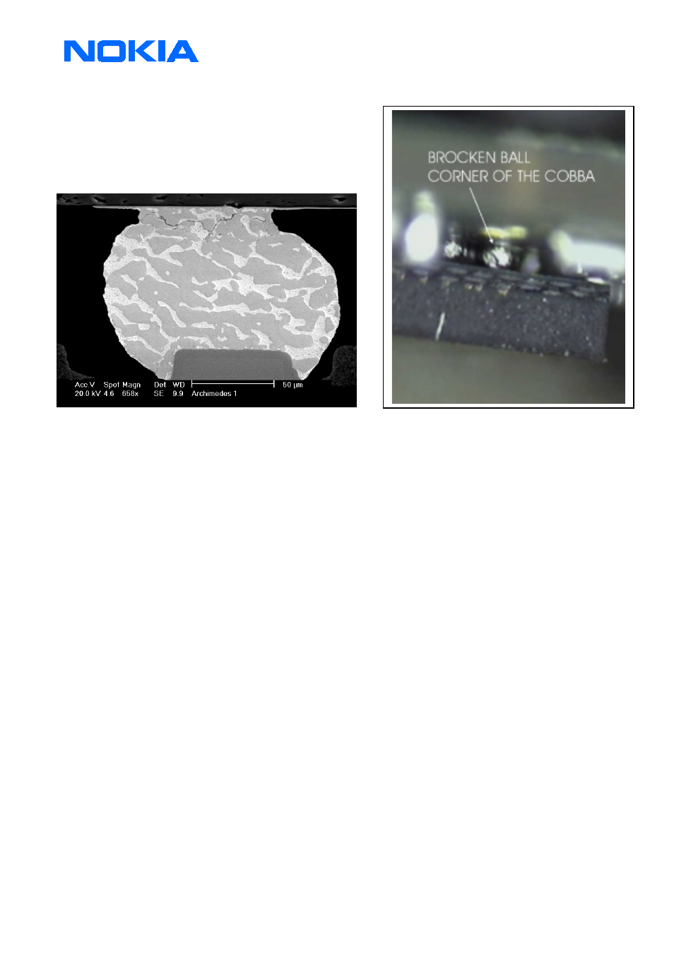
The pictures indicate a typically case of broken solder ball
under the μBGA. On the right you can see the little part of the
COBBA IC view with a microscope. The PCB is on the
top, and the COBBA are with the body to the bottom of
the picture. The picture below shows a broken ball view
through a X-ray machine
No TX-Power or to low
See also the troubleshooting chapter 4.GSM transmitter and 5. PCN transmitter from service manual
Z500 Duplexer Filter (Low TX-Power on GSM 900)
•
Check the TX-Power level between the TX "in" and "Antenna" pad of the duplexer
•
Resolder the ground and signal connection pads of the duplexer
•
Change the duplexer
Z504 RX/TX switch GSM1800 (Low TX-Power on GSM 1800)
•
Check the 1V DC TX-switching voltage on Z504
•
Check the TX-power difference between "TX" and "ANT" pad on Z504
•
Change the Z504 if more than 2dBm difference are measurable
N500 /N501 Power Amplifier GSM 900 /GSM 1800
•
Check the power supply VDC_OUT(3,2V
→
4,2V dependent to the power level) N500 /N501 pin 3
•
Check the input power on pin N500/ N501 depend of the band (nominal 0dbm)
•
Check the outgoing power on pin 4 N500/ N501
•
Check the TX-Power control signal on pin 2 N500/ N501 , 0,7Vpp-1,7Vpp / 0,12..V - 0,2..V DC dependent of the
power-level (see the diagram below)
•
Change the PA if no power or to low power comes out and the power supply and control line are OK