Nokia DNT2Mi sp/mp User Manual
Page 89
Using Q1 menus
DN01145897
© Nokia Corporation
89 (128)
Issue 2-0 en
Nokia Proprietary and Confidential
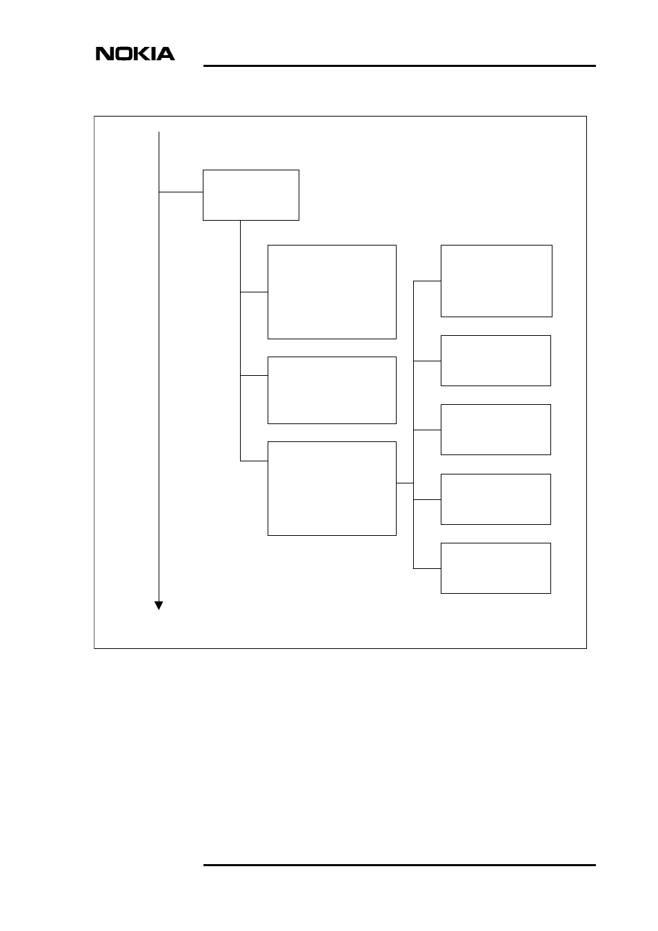
Figure 66.
Settings menu structure (continued), V-type adapters
6,4,port#,3
CT141 use:
0 Display
1 In use
2 Not in use
Sync/Async:
0 Display
1 Synchronous
2 Async 8 bits
3 Async 9 bits
4 Async 10 bits
5 Async 11 bits
CT103 timing:
0 Display
1 CT113 (DTE source)
2 CT114 (DCE source)
DTE circuits:
0 Display
1 RTS & CTS use
2 DCD use
3 DSR & DTR use
4 CT140 use
5 CT141 use
RTS & CTS use:
0 Display
1 CTS ON
2 RTS-CTS delay 8 bits
3 RTS-CTS delay 255 bits
4 Simulated carrier
DSR & DTR use:
0 Display
1 DTR controls DSR
2 DSR ON
CT140 use:
0 Display
1 In use
2 Not in use
6,4,port #,3,1
6,4,port #,3,2
6,4,port #,3,3
6,4,port #,3,3,1
6,4,port #,3,3,2
6,4,port #,3,3,3
6,4,port #,3,3,4
6,4,port #,3,3,5
V-type inteface settings:
V-type DTE:
1 Sync/async 1)
2 CT103 timing
3 DTE circuits
6,4,port#,3
1)
3 CT114 INV (DCE source) 2)
DCD use:
0 Display
1 Follows line sync
2 Simulated carrier
Only in ports 2 and 3 and if V.28
adapter and V.110 in use
2) Only in port 1