2 rear panel, Rear panel – Nokia DNT2Mi sp/mp User Manual
Page 19
Construction and interfaces
DN01145897
© Nokia Corporation
19 (128)
Issue 2-0 en
Nokia Proprietary and Confidential
4.2
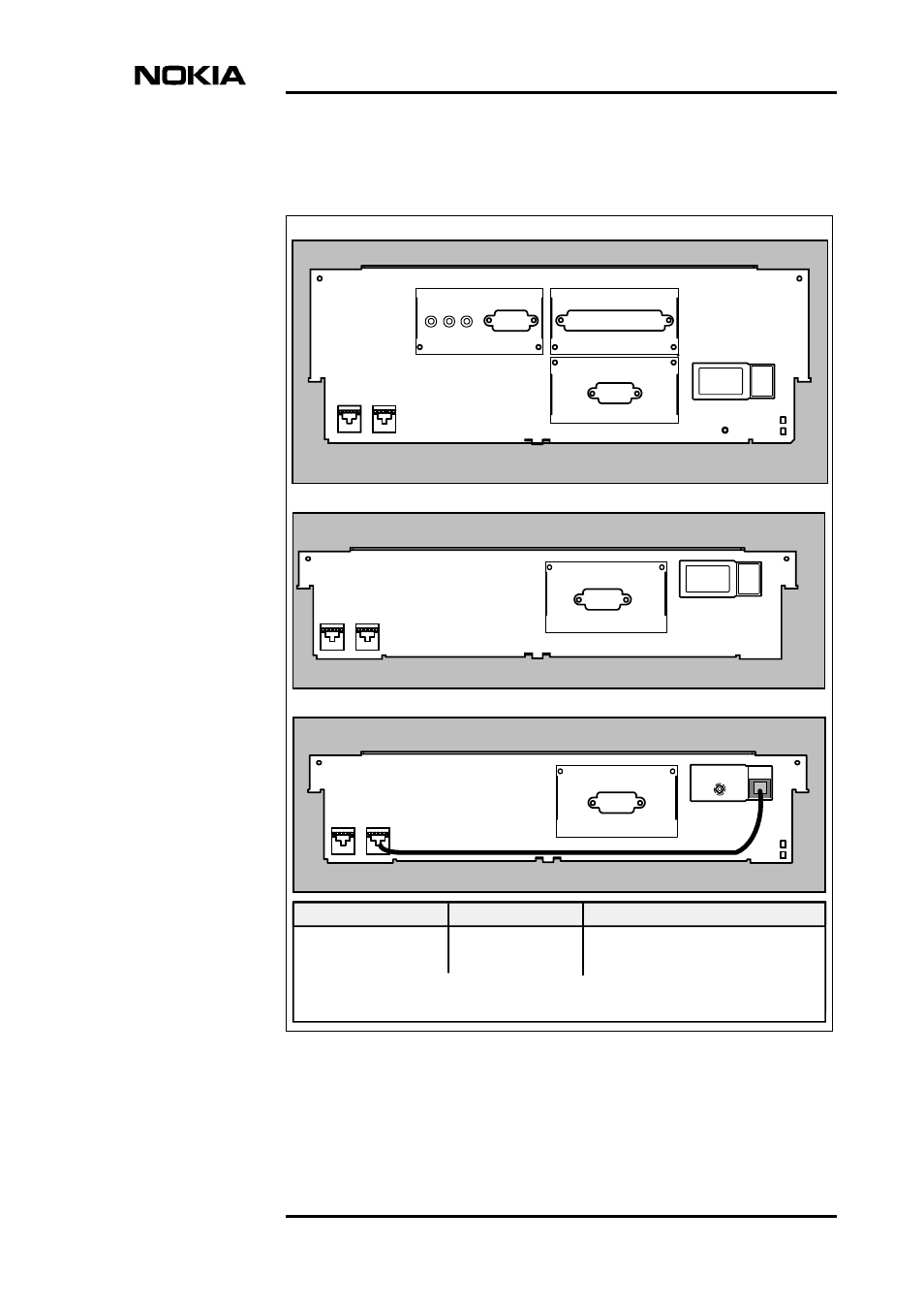
Rear panel
Figure 7.
Rear panels of the DNT2Mi units
1. a
3.
1.
b
Line
2.
2.
2.
G.704
V.11
X.21
4.
RPWR
2.
1. a
3.
Line
4.
RPWR
1.
b
Multiport DNT2Mi
Single-port DNT2Mi
The two upper
adapters are
upside down
2.
1.a
3.
Line
4.
RPWR
1. b
Remote-powered DNT2Mi
1. c
OUT
OUT
OUT
AC VERSION
DC VERSION
REMOTE-POWERED VERSION
1 a) Remote power input
c) Remote power input cable
1 a) Mains connection
b) Mains switch
1 a) DC connection
b) DC switch
2. DTE interfaces
3. Line interface, 2-wire or 4-wire
4. Remote power feeding output
X.21
X.21
b) Ground connection