3 sdio device connections, 4 unused pins – Nvidia TEGRA DG-04927-001_V01 User Manual
Page 34
Tegra 200 Series Developer Board User Guide
DG-04927-001_v01
Advance Information – Subject to Change
34
NVIDIA CONFIDENTIAL
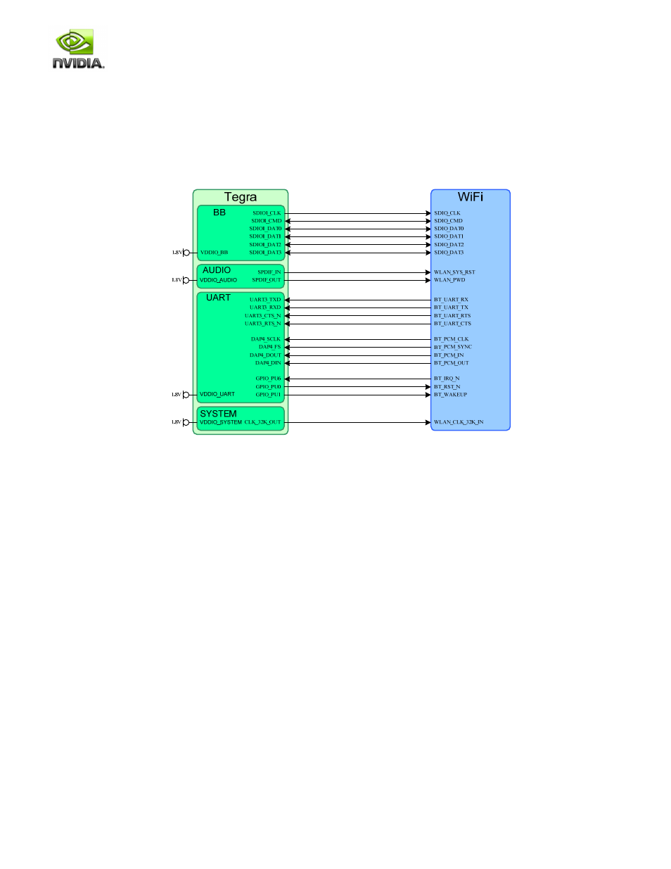
4.8.3 SDIO Device Connections
An SDIO controller is often used to interface to medium bandwidth peripherals such as a Wi-Fi controller. The connection
example in Figure 22 is from the Smartbook Development System. This shows a Wi-Fi/BT module interfacing to the Tegra 250
SDIO1, UART3 and DAP4 interfaces as well as several GPIO pins for control. Only the signals between the Tegra 250 and the
module are shown.
Figure 22. Tegra 250 SDIO WiFi Connection Example
4.8.4 Unused Pins
Any unused data pins can be left unconnected. If the HSMMC or SD/SDIO interfaces will not be supported at all, then any
unused signal pin can be left unconnected or configured for another function or GPIO. If none of the signals are used on one of
the digital power domains (except VDDIO_DDR and VDDIO_SYS which must be powered for normal operation), then the
associated power rail can be left unconnected or tied to GND.