2 i2c map, Figure 5. i2c diagram – Nvidia TEGRA DG-04927-001_V01 User Manual
Page 14
Tegra 200 Series Developer Board User Guide
DG-04927-001_v01
Advance Information – Subject to Change
14
NVIDIA CONFIDENTIAL
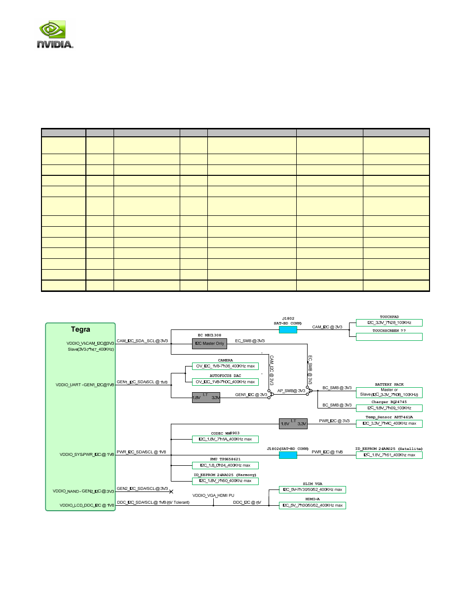
3.2 I2C Map
The I2C interface can be used to connect a touch screen, touch pad and other devices.
There are two options for the Touch devices. I2C versions of these devices (recommended) interface to the Tegra 250, while
PS/2 versions connect to the EC controller.
Table 3. Tegra 200 Series Developer Board I2C Map
Domain
Contrlr
Pins
Volt.
Device
ID / I2C Addr
Location
VDDIO_VI
I2C3
CAM_I2C_SCL/SDA
3.3V
MEC1308 (I2C Master)
Tegra 250 Slave addr:
0x45
Main Board
VDDIO_VI
I2C3
CAM_I2C_SCL/SDA
3.3V
Touchpad
0x28
Remote Location
VDDIO_VI
I2C3
CAM_I2C_SCL/SDA
3.3V
Touchscreen
TBD
Remote Location
VDDIO_UART
I2C1
GEN1_I2C_SCL/SDA
1.8V
Camera
0x36
Main Board
VDDIO_UART
I2C1
GEN1_I2C_SCL/SDA
1.8V
Autofocus DAC
0x0C
Main Board
VDDIO_UART
I2C1
GEN1_I2C_SCL/SDA
3.3V
Option for SMB to Battery Pack
Pack is Master or Slave
Slave addr: 0x0B
Main Board
VDDIO_UART
I2C1
GEN1_I2C_SCL/SDA
3.3V
Option for SMB to Charger
0x09
Main Board
VDDIO_LCD
I2C2
DDC_SCL/SDA
5.0V
Mini VGA or HDMI Display
0x30, 0x50, 0x52
Main Board
VDDIO_SYS
PWR_I2C PWR_I2C_SCL/SDA
1.8V
TI TPS658621 PMU
0x34
Main Board
VDDIO_UART
I2C1
1.8V
WM8903 Audio Codec
0x1A
Main Board
VDDIO_SYS
PWR_I2C
1.8V
ID EEPROM
0x50
Main Board
VDDIO_SYS
PWR_I2C
1.8V
ID EEPROM
0x51
Remote Location
VDDIO_SYS
PWR_I2C
1.8V
Temperature Sensor
0x4C
Main Board
Figure 5. I2C Diagram