Installation, Nti nodemux series universal kvm switch 5, Fig. 4b fig. 4a – Network Technologies ST-xU User Manual
Page 9: Rear view of nodemux, Damage may occur to the, If power is not disconnected before connecting or, Disconnecting cables, Keyboard symbol mouse symbol
NTI NODEMUX SERIES UNIVERSAL KVM SWITCH
5
INSTALLATION
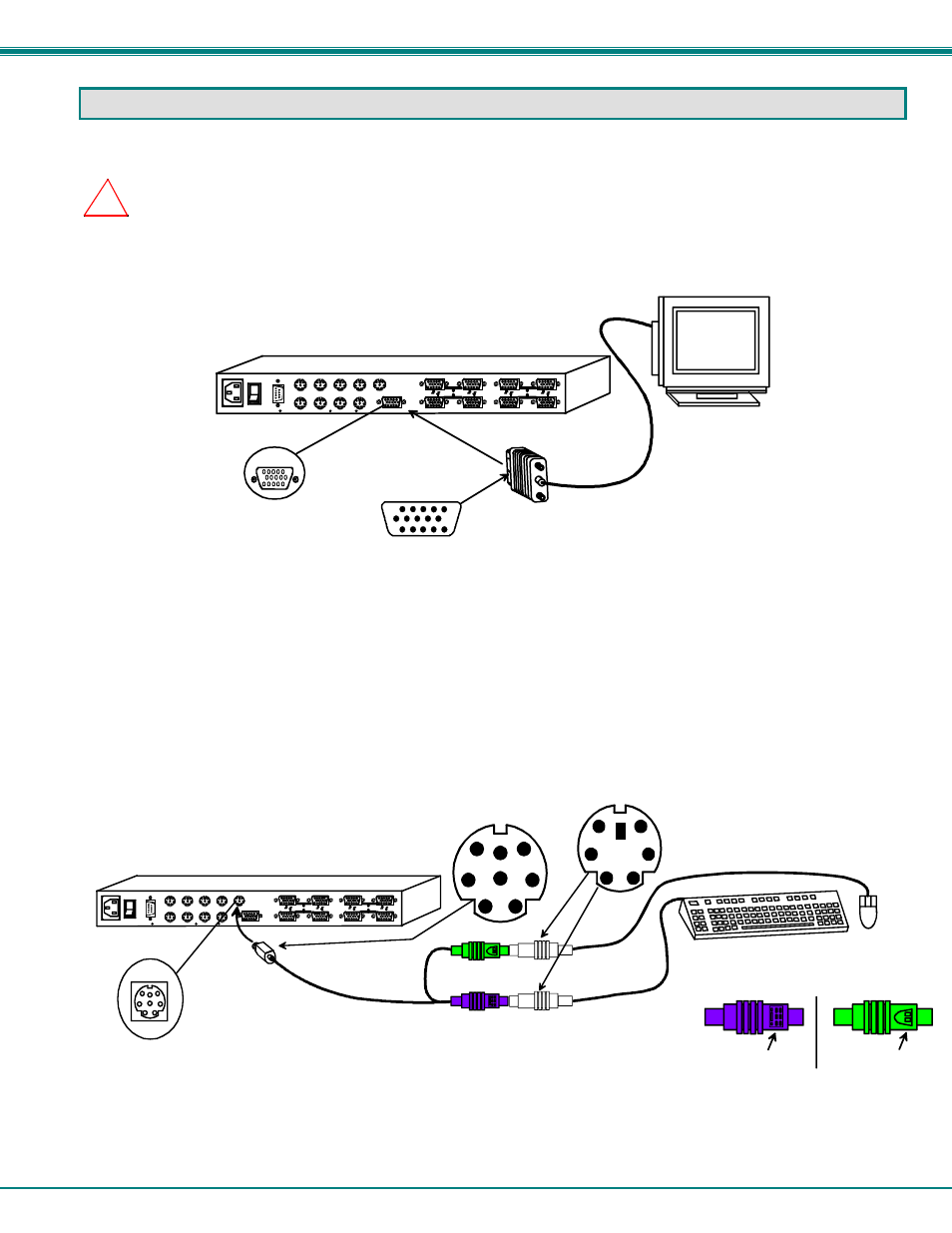
1. Turn OFF power to all CPUs that will be connected to the NODEMUX before connecting or disconnecting any cables to or
from them.
WARNING
!
DAMAGE MAY OCCUR TO THE
CPU
IF POWER IS NOT DISCONNECTED BEFORE CONNECTING OR
DISCONNECTING CABLES
.
2. Connect the monitor to the port labeled MONITOR on the rear of the NODEMUX.
Figure 3- Connect the monitor
3. Connect the input devices (keyboard/mouse) to the port labeled DEVICES on the rear of the NODEMUX following one of the
methods detailed below:
•
PS/2 keyboard and mouse- attach the 8-pin male end of a VKTINT-1 to the NODEMUX at the DEVICES port. The
keyboard will plug into the 6-pin purple female connector with the keyboard symbol on it (see Fig. 4a), and the mouse will
plug into the 6-pin green female connector with the mouse symbol on it (see Fig. 4b).
Figure 4- Connect a PS/2 keyboard and mouse
Fig. 4b
Fig. 4a
Keyboard Symbol
Mouse Symbol
!
DEVICES
8 Pin miniDIN Female
Connector
PS/2 Keyboard
VKTINT-1
PS/2
Mouse
6 Pin miniDIN Male
Connector
(GREEN)
(PURPLE)
8 Pin miniDIN Male
Connector
8 4
7 3
6 2
5 1
VIDEO
VIDEO
NETWORK TECHNOLOGIES INC
Tel:330-562-7070
1275 Danner Dr, Aurora, OH 44202
ww w.nti1.com
Rear View of NODEMUX
CPU 4
CPU 3
CPU 2
CPU 1
CPU 8
CPU 7
CPU 6
CPU 5
DEVICES
MONITOR
R
S
2
3
2
VGA
Multi-Scan
Monitor
MONITOR
15HD Male
Video Connector
15HD Female
Video Connector
8 4
7 3
6 2
5 1
VIDEO
VIDEO
NETWORK TECHNOLOGIES INC
Tel:330-562-7070
1275 Danner Dr, Aurora, OH 44202
www.nti1.com
Rear View of NODEMUX
CPU 4
CPU 3
CPU 2
CPU 1
CPU 8
CPU 7
CPU 6
CPU 5
DEVICES
MONITOR
R
S
2
3
2