Chapter 2 installation and configuration, Installing the network module, Figure 2-1. din rail clip in the unlocked position – National Instruments FP-1001 User Manual
Page 12: Figure 2-2. installing the network module onto a d, Installing the network module -1, Figure 2-1, Din rail clip in the unlocked position -1, Figure 2-2, Installing the network module onto a din rail -1, Installation and configuration
© National Instruments Corporation
2-1
FieldPoint FP-1000/FP-1001 User Manual
Chapter
2
Installation and
Configuration
This chapter describes how to install and configure your FieldPoint
network module, connect it to an RS-232 or RS-485 network, and
connect power to the network module.
Installing the Network Module
The FieldPoint network modules have rugged, simple clips for
mounting reliably onto a standard 35 mm DIN rail. Follow these steps
to mount the network module onto a DIN rail. Terminal bases must be
connected to the network module before power is applied.
1.
Use a flat-bladed screwdriver to open the DIN rail clip to the
unlocked position, as shown in Figure 2-1.
Figure 2-1. DIN Rail Clip in the Unlocked Position
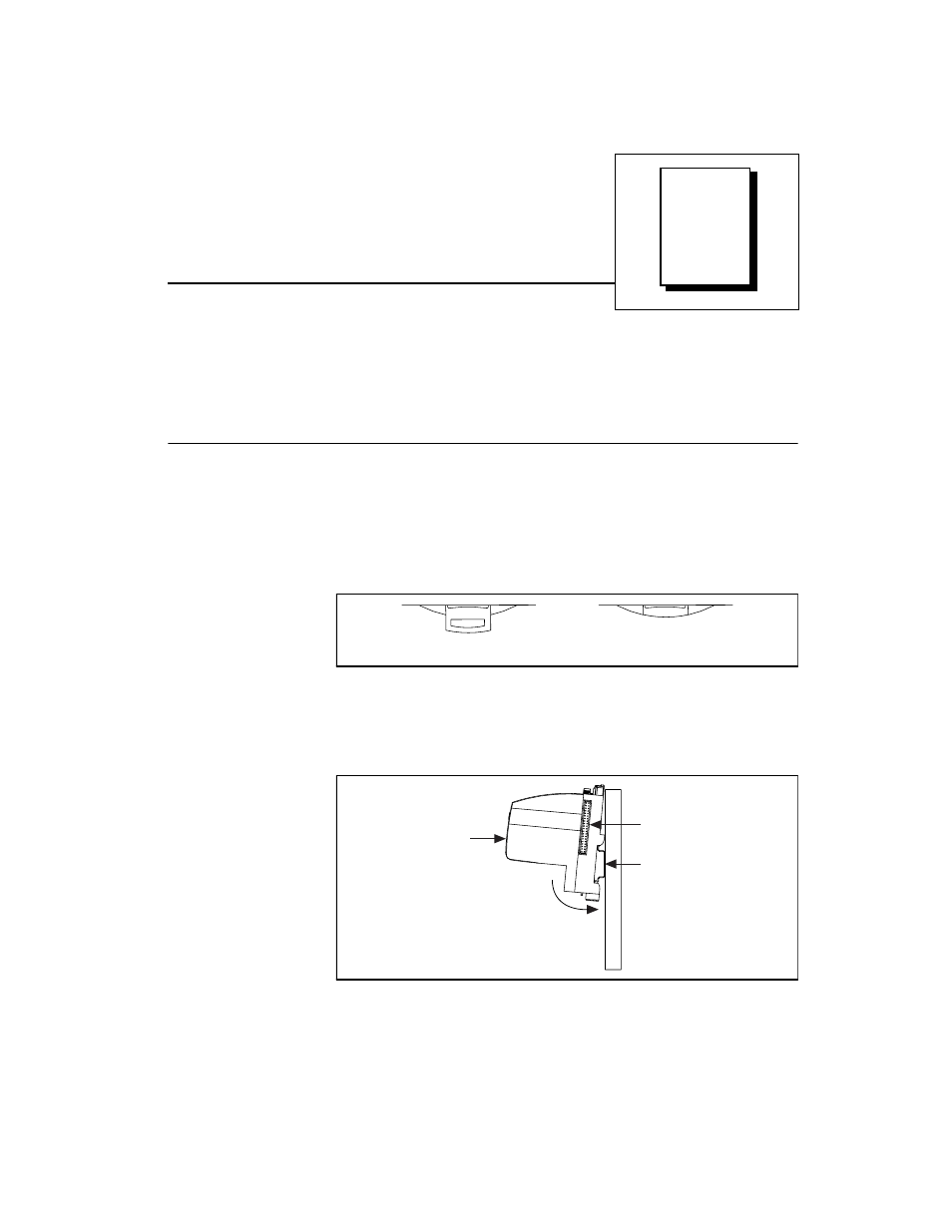
2.
Hook the lip on the rear of the network module onto the top of a
35 mm DIN rail and press the network module down onto the DIN
rail as shown in Figure 2-2.
Figure 2-2. Installing the Network Module onto a DIN Rail
Rail Clip Locked
Rail Clip Unlocked
Press
DIN Rail
Cover
Local Bus
Connector