Figure 4-25. wftrig input signal timing, Figure 4-26. wftrig output signal timing, Update* signal – National Instruments NI 6115/6120 User Manual
Page 67: Update* signal -30
Chapter 4
Connecting Signals
4-30
ni.com
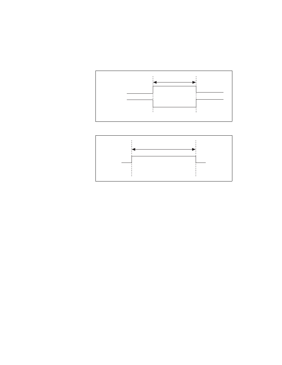
Figures 4-25 and 4-26 show the timing requirements for WFTRIG.
Figure 4-25. WFTRIG Input Signal Timing
Figure 4-26. WFTRIG Output Signal Timing
UPDATE* Signal
Any PFI pin can receive as an input the UPDATE* signal, which is
available as an output on the PFI5/UPDATE* pin.
As an input, UPDATE* is configured in the edge-detection mode. You can
select any PFI pin as the source for UPDATE* and configure the polarity
selection for either rising or falling edge. The selected edge of UPDATE*
updates the outputs of the DACs. In order to use UPDATE*, you must set
the DACs to posted-update mode.
As an output, UPDATE* reflects the actual update pulse that is connected
to the DACs, even if another PFI is externally generating the updates. The
output is an active low pulse with a pulse width of 50 to 75 ns. This output
is set to high-impedance at startup.
Rising-Edge
Polarity
Falling-Edge
Polarity
t
w
= 10 ns minimum
t
w
t
w
t
w
= 25 – 50 ns