Figure 4-22. sisource signal timing, Scanclk signal, Figure 4-23. scanclk signal timing – National Instruments NI 6115/6120 User Manual
Page 65: Scanclk signal -28
Chapter 4
Connecting Signals
4-28
ni.com
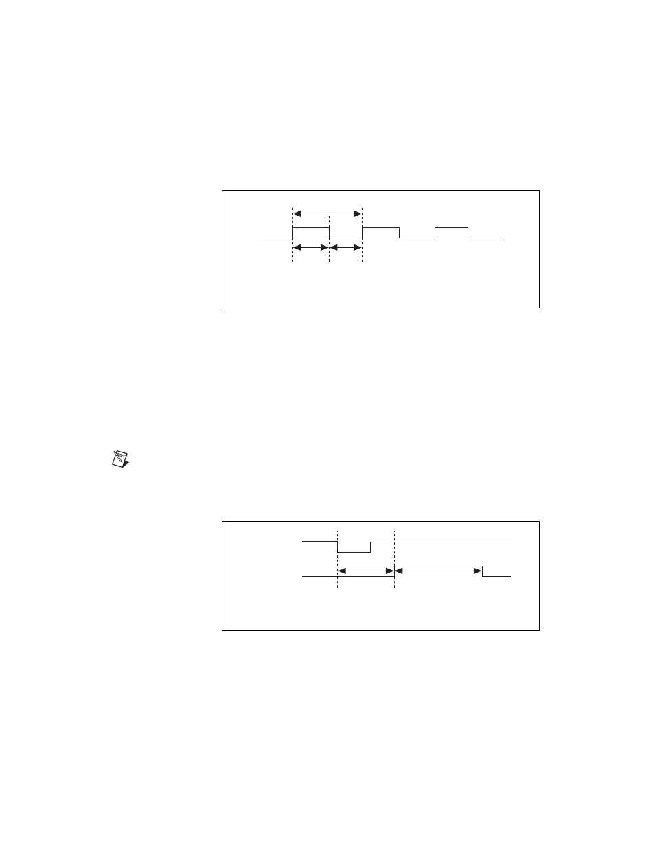
Either the 20 MHz or 100 kHz internal timebase generates SISOURCE
unless you select some external source. Figure 4-22 shows the timing
requirements for SISOURCE.
Figure 4-22. SISOURCE Signal Timing
SCANCLK Signal
SCANCLK is an output-only signal that generates a pulse with the leading
edge occurring approximately 50 to 100 ns after an A/D conversion begins.
The polarity of this output is software selectable but is typically configured
so that a low-to-high leading edge can clock external AI multiplexers
indicating when the input signal has been sampled and can be removed.
This signal has a 450 ns pulse width and is software enabled.
Note
When using NI-DAQ, SCANCLK polarity is low-to-high and cannot be changed
programmatically.
Figure 4-23 shows the timing for SCANCLK.
Figure 4-23. SCANCLK Signal Timing
t
p
= 50 ns minimum
t
w
= 23 ns minimum
t
w
t
w
t
p
t
d
= 50 to 100 ns
t
w
= 450 ns
t
d
CONVERT*
SCANCLK
t
w