Panel layout of imc-101 series – TREND IMC-101 User Manual
Page 6
— 2 —
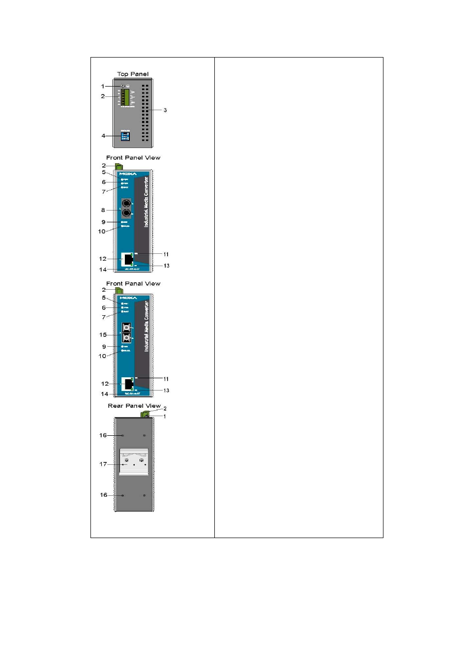
Panel Layout of IMC-101 series
1. Grounding
screw
2.
Terminal block for power input
PWR1/PWR2 and relay output
3.
Heat dissipation orifices
4. Dip
switch
5.
Power input PWR1 LED
6.
Power input PWR2 LED
7. Fault
LED
8.
100BaseFX (ST connector) Port
9.
FX port’s 100 Mbps LED
10. FX port’s Full Duplex/Collision LED
11. TP port’s 100 Mbps LED
12. 10/100BaseT(X)
13. TP port’s 10 Mbps LED
14. Model
Name
15.
100BaseFX (SC connector) Port
16. Screw hole for wall mounting kit
17.
DIN-Rail mounting kit
See also other documents in the category TREND Accessories for electrical:
- AV_D (4 pages)
- TB_TS_KE, _KEF (4 pages)
- RD-IQL (8 pages)
- SDU-LON (12 pages)
- TB_TS_K (4 pages)
- ENCLS_MBOX_IQ22x (4 pages)
- NBOX_XNC220 (12 pages)
- ENCLS_MBOX_IQ21x (2 pages)
- RD-IQ (8 pages)
- ACC_24VAC (2 pages)
- iQView4 (8 pages)
- IQ21x (12 pages)
- IQ22x (12 pages)
- ENCLS_... (2 pages)
- KIT_NODE_IQ23x (8 pages)
- IQ23x (36 pages)
- IQ246 (12 pages)
- KIT_NODE_IQ241 (8 pages)
- SCVO (8 pages)
- IQ241_242 (12 pages)
- KIT_NODE_IQ25x (8 pages)
- IQ251 (16 pages)
- PSR230_24 (4 pages)
- XCITE_IC (1 page)
- XCITE_TERM (1 page)
- XCITE_BBC (2 pages)
- EDS-305 (19 pages)
- EDS-205 (11 pages)
- XCITE_IO (16 pages)
- IQ3 User Guide (40 pages)
- IQ3..._..._XNC_... (8 pages)
- IQ3xact (16 pages)
- IQ3xcite (16 pages)
- SRMV (4 pages)
- IQ3.._..._LAN_... (4 pages)
- IQView.._SM (12 pages)
- IQView.._RPM (12 pages)
- IQVIEW_NDP (2 pages)
- RJ (11 pages)