Nortec NHTC User Manual
Page 37
10-10
Page 29
2008-10-01
Table 9. Typical Absorption Distances, Single Distributor, 100 lbs/hr Humidifier
FPM
°F
°C
% RH
FT
CM
Typical System
(V)
(T)
(H)
(D)
500
70
21
30
3.0
91
Air handler before coils
500
55
13
80
4.5
137
Air handler after cooling
900
70
21
30
3.5
107
Supply air duct, on cool, no heat
900
55
13
70
6.0
183
Supply air duct, on cool
1000
55
13
90
8.0
244
Supply air duct, on cool with high humidity
1000
110
43
10
2.5
76
Supply air duct, on heating with low humidity
1000
70
21
45
4.0
123
Return air duct conditions
2000
55
13
45
10.0
305
Supply air duct higher pressure system
5000
140
60
10
2.0
61
After operating heating coil
(V) = Velocity at distributor location (T) = Temperature at distributor location
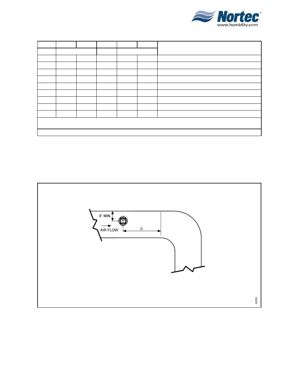
(D) = Absorption distance (visible steam) (H) = Humidity level after steam is absorbed
NOTE: This chart is for reference only; multiple distributors can reduce absorption distances.
Figure 3. Steam Distributor Location