30 mhz ac electrical characteristics – National Instruments HPC167064 User Manual
Page 5
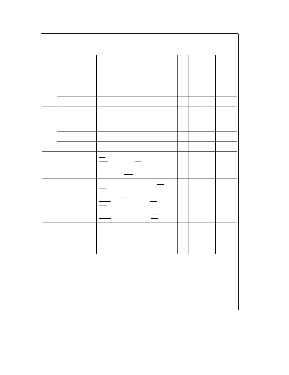
30 MHz
AC Electrical Characteristics
(See Notes 1 and 4 and
Figures 1
thru
5
) V
CC
e
5V
g
10% T
A
e
0 C to a70 C for HPC467064
Symbol and Formula
Parameter
Min
Max
Units
Notes
f
C
CKI Operating Frequency
2
30
MHz
t
C1
e
1 f
C
CKI Clock Period
33
500
ns
t
CKIH
CKI High Time
22 5
ns
t
CKIL
CKI Low Time
22 5
ns
t
C
e
2 f
C
CPU Timing Cycle
66
ns
t
WAIT
e
t
C
CPU Wait State Period
66
ns
t
DC1C2R
Delay of CK2 Rising Edge after CKI Falling Edge
0
55
ns
(Note 2)
t
DC1C2F
Delay of CK2 Falling Edge after CKI Falling Edge
0
55
ns
(Note 2)
f
U
e
f
C
8
External UART Clock Input Frequency
3 75
MHz
f
MW
External MICROWIRE PLUS Clock Input Frequency
1 875
MHz
f
XIN
e
f
C
22
External Timer Input Frequency
1 364
MHz
t
XIN
e
t
C
Pulse Width for Timer Inputs
66
ns
t
UWS
MICROWIRE Setup Time
Master
100
ns
MICROWIRE Setup Time
Slave
20
t
UWH
MICROWIRE Hold Time
Master
20
ns
MICROWIRE Hold Time
Slave
50
t
UWV
MICROWIRE Output Valid Time
Master
50
ns
MICROWIRE Output Valid Time
Slave
150
t
SALE
e
t
C
a
40
HLD Falling Edge before ALE Rising Edge
90
ns
t
HWP
e
t
C
a
10
HLD Pulse Width
76
ns
t
HAE
e
t
C
a
85
HLDA Falling Edge after HLD Falling Edge
151
ns
(Note 3)
t
HAD
e
t
C
a
85
HLDA Rising Edge after HLD Rising Edge
135
ns
t
BF
e
t
C
a
66
Bus Float after HLDA Falling Edge
99
ns
(Note 5)
t
BE
e
t
C
a
66
Bus Enable after HLDA Rising Edge
99
ns
(Note 5)
t
UAS
Address Setup Time to Falling Edge of URD
10
ns
t
UAH
Address Hold Time from Rising Edge of URD
10
ns
t
RPW
URD Pulse Width
100
ns
t
OE
URD Falling Edge to Output Data Valid
0
60
ns
t
OD
Rising Edge of URD to Output Data Invalid
5
45
ns
(Note 6)
t
DRDY
RDRDY Delay from Rising Edge of URD
70
ns
t
WDW
UWR Pulse Width
40
ns
t
UDS
Input Data Valid before Rising Edge of UWR
10
ns
t
UDH
Input Data Hold after Rising Edge of UWR
20
ns
t
A
WRRDY Delay from Rising Edge of UWR
70
ns
t
DC1ALER
Delay from CKI Rising Edge to ALE Rising Edge
0
35
ns
(Notes 1 2)
t
DC1ALEF
Delay from CKI Rising Edge to ALE Falling Edge
0
35
ns
(Notes 1 2)
t
DC2ALER
e
t
C
a
20
Delay from CK2 Rising Edge to ALE Rising Edge
37
ns
t
DC2ALEF
e
t
C
a
20
Delay from CK2 Falling Edge to ALE Falling Edge
37
ns
t
LL
e
t
C
b
9
ALE Pulse Width
24
ns
t
ST
e
t
C
b
7
Setup of Address Valid before ALE Falling Edge
9
ns
t
VP
e
t
C
b
5
Hold of Address Valid after ALE Falling Edge
11
ns
Clocks
Timers
MicrowirePlus
External
Hold
UPI
Timing
Address
Cycles
5