20 mhz ac electrical characteristics – National Instruments HPC167064 User Manual
Page 4
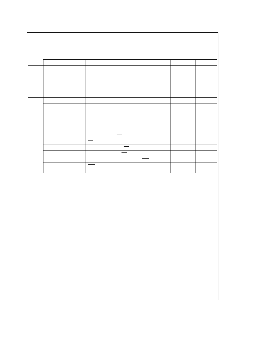
20 MHz
AC Electrical Characteristics
(Continued)
(See Notes 1 and 4 and
Figures 1
thru
5
) V
CC
e
5V
g
5%
T
A
e b
55 C to a125 C for HPC167064 and V
CC
e
5V
g
10%
T
A
e
0 C to a70 C for HPC467064 (Continued)
Symbol and Formula
Parameter
Min
Max
Units
Notes
t
DC1ALER
Delay from CKI Rising Edge to ALE Rising Edge
0
35
ns
(Notes 1 2)
t
DC1ALEF
Delay from CKI Rising Edge to ALE Falling Edge
0
35
ns
(Notes 1 2)
t
DC2ALER
e
t
C
a
20
Delay from CK2 Rising Edge to ALE Rising Edge
45
ns
t
DC2ALEF
e
t
C
a
20
Delay from CK2 Falling Edge to ALE Falling Edge
45
ns
t
LL
e
t
C
b
9
ALE Pulse Width
41
ns
t
ST
e
t
C
b
7
Setup of Address Valid before ALE Falling Edge
18
ns
t
VP
e
t
C
b
5
Hold of Address Valid after ALE Falling Edge
20
ns
t
ARR
e
t
C
b
5
ALE Falling Edge to RD Falling Edge
20
ns
t
ACC
e
t
C
a
WS b 55
Data Input Valid after Address Output Valid
145
ns
t
RD
e
t
C
a
WS b 65
Data Input Valid after RD Falling Edge
85
ns
t
RW
e
t
C
a
WS b 10
RD Pulse Width
140
ns
t
DR
e
t
C
b
15
Hold of Data Input Valid after RD Rising Edge
0
60
ns
t
RDA
e
t
C
b
15
Bus Enable after RD Rising Edge
85
ns
t
ARW
e
t
C
b
5
ALE Falling Edge to WR Falling Edge
45
ns
t
WW
e
t
C
a
WS b 15
WR Pulse Width
160
ns
t
V
e
t
C
a
WS b 5
Data Output Valid before WR Rising Edge
145
ns
t
HW
e
t
C
b
5
Hold of Data Valid after WR Rising Edge
20
ns
t
DAR
e
t
C
a
WS b 50
Falling Edge of ALE to Falling Edge of RDY
75
ns
t
RWR
e
t
C
RDY Pulse Width
100
ns
Address
Cycles
Read
Cycles
Write
Cycles
Ready
Input
4