Fig 18 plus fig 19, Nxp semiconductors – NXP Semiconductors UM10301 PCF2123 User Manual
Page 42
NXP Semiconductors
UM10301
User Manual PCF85x3, PCA8565 and PCF2123, PCA2125
UM10301_1
© NXP B.V. 2008. All rights reserved.
User manual
Rev. 01 — 23 December 2008
42 of 52
mgm665
SCL
SDA
V
SS
OSCI
OSCO
CLOCK CALENDAR
PCF8563
SDA
SCL
MASTER
TRANSMITTER/
RECEIVER
V
DD
V
DD
SDA
SCL
R
R
V
DD
(I
2
C-bus)
R: pull-up resistor
R =
1 F
t
r
C
b
100 nF
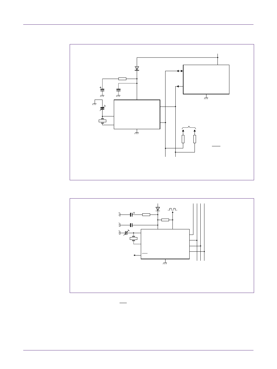
Fig 18. Application diagram 1, I
2
C-bus interface
The following example is with PCA2125 and SPI interface.
001aaf918
OSCI
1 F
supercapacitor
100 nF
OSCO
INT
V
SS
V
DD
CLKOUT
CE
SCL
SDI
SDO
PCA2125
The 1 Farad capacitor is used as a standby/backup supply. With the RTC in its minimum power
configuration i.e. timer off and CLKOUT off, the RTC may operate for several months.
Fig 19. Application diagram 2, SPI interface
Remark: CLKOUT and INT are open drain outputs. If a pull-up resistor is used, it should
not be connected to voltages higher than the maximum operating voltage as specified for
the RTC. If the outputs need to be used to switch signals connected to a higher potential,
it is necessary to use an external transistor.